I recently added 1.0uF as bypass cap for an o/p stage, everything becomes much clearer but with strange character to the sound . When I add 0.1R in series with the 1.0uF then the sound is clean again.
In spice the effect ( and the cure ) can be clearly seen. Not sure how much this applies to an o/p cap but the laws of physics cannot be escaped - if you add C & L with low R you have high Q at resonant frequency.
Hi Mike,
could you kindly post a realistic spice simulation of this. Such simulation should cover the amp under test (for the reason that a realistic output impedance must be taken into account), models of both electrolytic cap and foil cap (for foil cap, please use Roederstein 3.3uF MKT with axial leads, MKT1813 type) and a cable + speaker models. None of the components should be omitted for the reason to get a kind of reliable result.
Thanks,
Last edited:
Hi Pavel,
When I chose a bypass cap as an example of spurious resonance I was not thinking of your o/p arrangement - only after I post I realise this may seem like a pointed comment but actually, as I mentioned earlier, I was thinking of an o/p stage bypass cap - very common even in simple amps.
I cannot do the research you mention - don't have the models, the time, or the inclination. It may be you do not have a problem and if you don't that's great.
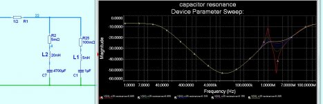
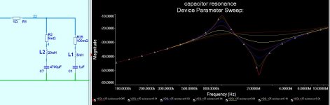
I show below the general spice research I did to explain to myself ( again ) the cause of the roughness I heard with 1uF bypassing 470uF ( with other caps upstream ) The findings shown match what my ears clearly hear
This graph shows AC sweeps. The 1uF bypass cap with R sweeping between .005R & .205R.
I have the feeling this is not news to you - but may be to others
Whoops - I post 4700uF but actually it makes little difference - the principal is clearly shown
When I chose a bypass cap as an example of spurious resonance I was not thinking of your o/p arrangement - only after I post I realise this may seem like a pointed comment but actually, as I mentioned earlier, I was thinking of an o/p stage bypass cap - very common even in simple amps.
I cannot do the research you mention - don't have the models, the time, or the inclination. It may be you do not have a problem and if you don't that's great.
I show below the general spice research I did to explain to myself ( again ) the cause of the roughness I heard with 1uF bypassing 470uF ( with other caps upstream ) The findings shown match what my ears clearly hear
This graph shows AC sweeps. The 1uF bypass cap with R sweeping between .005R & .205R.
I have the feeling this is not news to you - but may be to others
Whoops - I post 4700uF but actually it makes little difference - the principal is clearly shown
Attachments
Last edited:
Mike,
a resonance of a capacitor with inductance of lead conductors is normal, standard phenomenon.
But, your simulation may be pretty misleading for unexperienced diyers, for the reason that there is a speaker impedance in series with output capacitors.
Your simulation fits in case that you put a capacitor across amplifier output terminals (directly to ground). Then, as every amp designer knows, we see damped resonance (ringing) caused by wire inductance and capacitor capacitance.
I am sure that ESR and ESL of the output capacitors do not cause any ringing, when driven from real amplifier output and loaded by real electrodynamic speaker. Please note that I do not speak about AMPLIFIER instability and oscillations, but just about RLC.
Hi Mike,
I am sorry if I confused the issue, but what I refer to is
I understood that it was related to output capacitor (bypass for an o/p stage). I am sorry if I was wrong.
Regarding supply rails decoupling, I agree, this is a real science.
I am sorry if I confused the issue, but what I refer to is
But the ears can hear.
I recently added 1.0uF as bypass cap for an o/p stage, everything becomes much clearer but with strange character to the sound . When I add 0.1R in series with the 1.0uF then the sound is clean again.
I understood that it was related to output capacitor (bypass for an o/p stage). I am sorry if I was wrong.
Regarding supply rails decoupling, I agree, this is a real science.
Regarding simplicity measures, the TSSA basic is even simpler design and according to Sonnya measurements, and I believe they are correct, its results are even better than JLH 10 class A amplifier.")
Just looked again at what I understand are real world fourier results for Pavel's JLH & Sonnys's TSSA and unless I am missing something I would say the JLH figures are more impressive - lower noise floor & total absence of higher order harmonics.
I'm curious to know why you thought the opposite - did I miss something ?
mike
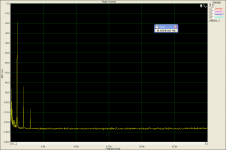
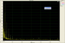
I would like to add that JLH distortion results strongly depend on supply voltage and idle current, for the same load. Please note that most of my measurements are for single supply voltage of only +27V and idle current of "only" 1A. The dynamic range is also affected by a measurement method. One can clearly see effect of FFT resolution in the two attached images. One with resistor divider in front of the soundcard and the 2nd without the divider. Please note that lines around 15kHz and 19kHz are TV line freq. and FM radio pilot freq. induced to the high-sensitive setup. Frequencies at 25kHz and higher result from digital soundcard circuitry. Load and Vpp can be read from image file names.
I am very sorry I cannot follow the discussion now, as i am very busy with another project field.
Regards,
I am very sorry I cannot follow the discussion now, as i am very busy with another project field.
Regards,
Attachments
Just looked again at what I understand are real world fourier results for Pavel's JLH & Sonnys's TSSA and unless I am missing something I would say the JLH figures are more impressive - lower noise floor & total absence of higher order harmonics.
I'm curious to know why you thought the opposite - did I miss something ?
mike
From pics it is obvious that measuring "environment" of Sonnya's equipment has inherent noise floor at -100 dB, or it can be the noise floor of uncompensated, no low pass filter treated amp. That's really not so important, cause it's to low to affect real life performance. Also it can be mostly sorted out with good power supply etc.
What I was mainly concentrated were spectral components, ratio of higher order presence and their suppression. Measurement conditions were different so not so reliable comparison after all.
TSSA was without any reference point in the circuit (sch from the post#1 in TSSA thread), two simple CCSs added would rocketed performance surely.

Mike please don't misunderstand me, I'm very glad that we explore different amps and exchange our experiences, that's the most important thing.
P.S. Our DIY community here is so precious, cooperative, that I don't regret energy and any second spent on the forum, and there were quite amount of them spent here.

Last edited:
Hey PMA,
Given the importance of the output coupling caps, I was just about to ask what you are using.
You mentioned the bypass was Roederstein MKT1813 3.3uF, I assume you mean the 63V part.
MKT1813533064 Vishay/Roederstein DC Link Film Capacitors
For my friendly Southern neighbours, look it up on the US mouser site. (Yes, that's how we spell "neighbours")
PMA, what electrolytic are you using?
I realize you're taking some time off, but I hope you stop by ...
(Maybe I'll check the pics at the beginning of the thread and see if I can read it)
Cheers,
Jeff
Please note that lines around 15kHz and 19kHz are TV line freq. and FM radio pilot freq. induced to the high-sensitive setup. Frequencies at 25kHz and higher result from digital soundcard circuitry.
I always do fourier analysis in spice up to 20khz and I always have a high reading at 19khz.
Strange to see it there exactly the same in your real world analysis - so it may be something to do with using computers for analysis ? ? ?
I do not believe it is real
mike
PCB needed
I am ready now to start a new project.
I have long time dreamed to make a JLH, possibly the single power version, with TO3s.
I have most of thye components, so, since I do not intend to make changes to the classic circuit, I am looking for a ready - made PCB. Do you know a good source ?
I am ready now to start a new project.
I have long time dreamed to make a JLH, possibly the single power version, with TO3s.
I have most of thye components, so, since I do not intend to make changes to the classic circuit, I am looking for a ready - made PCB. Do you know a good source ?
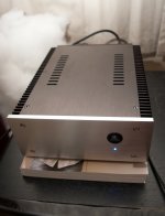
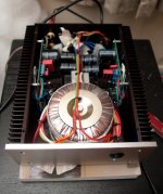
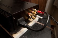
My JLH is all cased up and running well
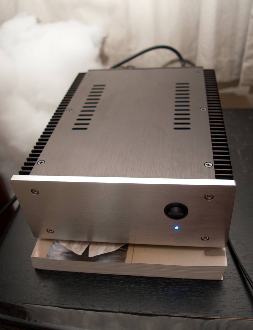
Looks pretty good
Where did you get the casing and what psu are you running?
Kenneth
- Home
- Amplifiers
- Solid State
- JLH 10 Watt class A amplifier