I am trying to adjust the tempco of the input transistor and it's CCS to minimise drift in the output offset.
I have been at it for over 4 hours today and a couple of hours yesterday and I'm not in the ballpark yet. I think I am getting closer.
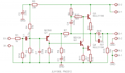
Andrew, I want to keep the original capacitively coupled version. One of the reasons is the possible output DC offset instability, and frankly speaking I do not like the 'improved' circuit designs that appeared after the original version. I bypassed the output capacitor with the 3u3 high quality foil type, and added 2 resistors - 1st to discharge input capacitor to ground (1M) and 2nd to discharge output capacitor when load is disconnected (10k). I also had to add 220pF capacitor + 1k resistor as an input RC, for the reason of faster modern devices used, it was necessary. Output devices are MJL21194 and they do a great job.
Hi kp93300. Noticed your post #2349 re; bias adjustment. I am not sure if you particularly want to use the original 1969 circuit but JLH put out an amended design the following year with a better system for the bias. Are you aware of Geoff Moss's site that is about 95% JLH Class A? Mountain of info' on this amp. Just Google "Class-A amp site" and it should come up. Cheers, Jonathan
Last edited:
The bootstrap resistors should be equal, for least parasitic load on the output.
I have no idea why JLH's resistors are unequal. 355 + 355 would give the same
series resistance and current, but roughly half the parasitic load of 150 + 560.
The corner frequency is lower for the same value bootstrap cap too.
I have no idea why JLH's resistors are unequal. 355 + 355 would give the same
series resistance and current, but roughly half the parasitic load of 150 + 560.
The corner frequency is lower for the same value bootstrap cap too.
Last edited:
I am trying to adjust the tempco of the input transistor and it's CCS to minimise drift in the output offset.
I have been at it for over 4 hours today and a couple of hours yesterday and I'm not in the ballpark yet. I think I am getting closer.
Andrew dont forget to temp compensate the current source as well, only way youll get it 100 percent stable, if youre using the 2 transistor ccs, you could just use a low voltage zener in series with the controlling transistor, zeners have closer tempco with transistors.
Yes I said input transistor and it's CCS.
Last night I gave up with the PCB as is and started to thermally couple Q4 to Q5, but the leg lengths I left were too short (by about 1mm each).
I am not ready to build up the second PCB so Today I will replace those two transistors and thermally couple them to see if that makes a difference.
It is certainly very clear that Q4 moves the offset in one direction and Q5 moves the offset in the opposite direction. And that Q3, Q5, Q6, Q7 and Q8 have a minor effect in comparison to the strong effect of 4&5. I have added a sink to Q8 since it dissipates ~ twice as much heat as Q3.
I am away looking for the link to the schematic.
I had to report my own unfinished post and this is what I sent.
your 30minute edit window expired before I could find and attach the link to the schematic. Why?
Because your system went into daytime maintenance and I had to wait and wait and wait before the Forum would talk to me again.
Please stop ******* us non USA Members about.
Substitute this wording for my unfinished post.
Yes I said input transistor and it's CCS.
Last night I gave up with the PCB as is and started to thermally couple Q4 to Q5, but the leg lengths I left were too short (by about 1mm each).
I am not ready to build up the second PCB so Today I will replace those two transistors and thermally couple them to see if that makes a difference.
It is certainly very clear that Q4 moves the offset in one direction and Q5 moves the offset in the opposite direction. And that Q3, Q5, Q6, Q7 and Q8 have a minor effect in comparison to the strong effect of 4&5. I have added a sink to Q8 since it dissipates ~ twice as much heat as Q3.
http://www.diyaudio.com/forums/solid-state/3075-jlh-10-watt-class-amplifier-3.html#post81619
link to the schematic. I am using the MJ15003, BD139/140 & BC560c semiconductor options.
I have no problem with DC servos.Do you have problem with dc servos, easiest solution.
I contributed to one of the most detailed discussions on DC servos ever held on this Forum.
But the JLH inherently suits AC coupling in it's original form.
The dual polarity version cries out for some form of build that is inherently offset stable.
That is what I am hoping to get closer to.
This same misbehaviour is seen in other circuits and if I can get a handle on this one, I may be able to transfer some of the lessons learned to other cases. I am somewhat in awe at Roender's tempco additions, my mind struggles with that even though he has shown me the answers.
It is likely I will never use this circuit to power a full range nor a bass only speaker. In this case I am likely to revert to the AC coupled single polarity version to drive treble and mid units which need the output capacitor anyway.
I think some forget, that I have two reasons for being here. To learn and to share.
I did a simulation using Bensen's spreadsheet for the MJ15003 outputs.
I was very surprised at how hard this single pair output stage can be pushed.
I found that an 8ohm 60degree reactance load using 60V supply rail (or +-30Vdc when biased) and running Tc @ 145°C could be driven while staying inside the voltage and temperature de-rated SOAR.
It was predicting 36W (all in ClassA if Ib=2A) safely into a reactive 8ohm speaker load.
Leaving a 45C degrees safety margin and using Tc~100°C allows a heatsink to run @ ~80°C. This would indicate that 2A bias for 120W of Pq would be possible with a big enough heatsink. Maybe around 0.3C/W to 0.5C/W
But it is going to burn anyone that touches it.
The bootstrap resistors should be equal, for least parasitic load on the output.
I have no idea why JLH's resistors are unequal. 355 + 355 would give the same
series resistance and current, but roughly half the parasitic load of 150 + 560.
The corner frequency is lower for the same value bootstrap cap too.
The load on the output shouldn't be a major concern because the loudspeaker load dominates.
Reducing the 560 ohm resistor lowers the impedance of the bootstrap current source, reducing or cancelling the benefit of the lower corner frequency.
Just for the record, this is the schematics as I have built it. I will keep the amplifier, at least for some time of listening tests.
Are you running it on +40Vdc as per your earlier shcematic, #2351? Can you share some details on your power supply?
EDIT: Also, why 1M for R14? Wouldn't there be noise benefits for dropping this to 100K or 47K?
Or, is the input impedance dominated by R2//R4?
Last edited:
Are you running it on +40Vdc as per your earlier shcematic, #2351? Can you share some details on your power supply?
EDIT: Also, why 1M for R14? Wouldn't there be noise benefits for dropping this to 100K or 47K?
Or, is the input impedance dominated by R2//R4?
I tried 27V and 42V PSU. Total filter capacitance is 27200 uF.
R14 is effectively shunted by output impedance of the preceding preamplifier (and by R2//R4). It has no noise contribution. You cold make it 100 Mohm as well without any noise difference, or in case you omitt it than R14 = infinity - again you would not consider it in noise calculations. Only R1 (1 kohm) counts for noise. The only reason to use the R14 is to keep C1 grounded when input is disconnected. This is very important to avoid thump impacts.
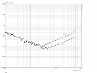
Several measurements for a version with power supply voltage +27V, one toroidal center tapped transformer 300VA, two separated bridge rectifiers and filters, one per each channel. Capacitor bank 20400 uF per channel (3 x 6800uF). Common ground for two channels. Idle current 1A per channel.
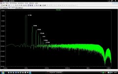
As one can see, THD depends on voltage (amplitude), but is almost independent on frequency. This is IMO very important. The circuit has OLG about 54 dB with frequency corner above 100kHz. This explains why THD does not depend on frequency in audio range.
After years, it is still very competitive design, in case its limited power is sufficient for the user. As long as JLH plays within its power limits, it sounds very good and will surpass most of contemporary class AB amplifiers.
Attachments
Last edited:
I built the JLH amplifier in the middle of 1970's and I remember that it was was a real breakthrough, compared to usual class B and AB designs of those days. It sounded very clean, full and natural.
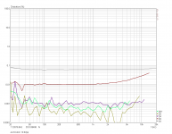
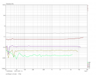
It is a wonderful design even today. I attempted a simulation on the original design running on only 17 volts into 5 ohms and the distortion plot to me highlights why it's so good sonically. The plot says it all really with the distortion just fading into the noise floor. And it's not a low distortion design by any means.
If I could achieve this at 100ma quiescent I would be very happy
")
Attachments
It is often said that even harmonics cancel in push pull amplifiers. The JLH, by itself, (single channel) does not act like a push pull amplifier. But when you use them in a bridge drive configuration, they do. Symetrical bending of the input signal generates odd order harmonic distortion and the even order distortion is canceled.
- Home
- Amplifiers
- Solid State
- JLH 10 Watt class A amplifier