Just tried BDW93C which I think were used in Creek CAS4040.
Slightly better. Up to 2A might be OK. The 1000 uF + 1000 uF is down do the noise floor at the Darlington base. Circa -100 dBV and output - 80dBV. The massive 22 000 uF computer grade caps give - 20 dBV. Thus this simple idea gives 60 dB hum reduction. A ready made if you are vastly experianced gives slightly more. What I doubt is the ready made sounds as good.
All this data comes from me having finally moved into my new house and having put parts into a new set of storage draws. I had no idea I had 2SC5200 and a nice number of them.
With new things there often is a learning curve. The JLH could work with the standard TL431 shunt regulator with power transistor. Class A is more suitable for shunt.. It is so well explained that success seems possible. It could sound better.
My zener idea is shunt zener with series current booster.
My zener idea is shunt zener with series current booster.
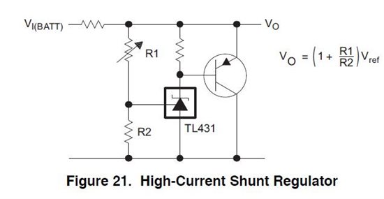
This is a concept ( see data sheet ). It migh be OK with a high speed device as they usually are good on gain and TL431 has reasonable current output. If you read the data sheet it could be unbeatable, if you don't it will be trouble. I think ON semiconductors are quietest. Slightly better that an LM 317 which is best of the cheaper things. My regulator is about like a LM78 device. It would be easy to make it better.
I didn't use TL431 for my idea for two reasons. It can be tricky if people treat it as a zener ( read the capacitance needs, use lower values I think ). My teacher in the early 1970s said the simple zener was obsolete. We did 90% valves as learning so a big deal he said it. So glad I did valves. We did transistors at the end of the subject and mostly the valves covered it. I remember being told that it is surprising how similar valves and transistors look when in fact things are different. We were never told exactly about enhancement devices.
Peter tried to teach Ferme levels. Half way through the lesson I said " Mr Platt what are you talking about " . He said " Not a clue ". My little brother taught me. I really liked Peter for that and he was a supurb teacher. He said " You guys mostly have been carrying me because you already know this stuff ". How far from the truth that was. He taught the stuff that is closer to science. My brother could have taught him in five minutes that bit. It's a great interest of mine due to this. I class metals as semiconductors especially aluminium. At super conducting levels the clouds in the sky hits the ground in analogy so that the Ferme voltage is zero. Fog=cloud so to speak. I have worked in this. Current limitations show super conducting has odd qualities.

This was the BD139+ 2SC5200 when it was working. 90% of the time it wasn't ( 10 MHz 20 mV and other things ). I can almost guarantee the bad version is what you will get. It would be very good if it could be trusted. Too much gain, too much bandwidth? I could solve this but it wouldn't the simple idea requested. If I was making a class AB amplifier I think I would use a ready made Darlington.

This was the excellent version that shouldn't work. It just about does work. Regulation is good but not as good as the TIP142/147.
This is not Darlingtons. It looks the same except I have put a diode in as a heavy hint ( 6 A ). Notice hiss is -102 dBV just like a good regulator. I would image a single 2SC5200 should work. The 18.1 to 18.48 V was the TIP142/7.
I assumed you expected that was the case before you began the experiment and you were just playing with parts for fun... Well, it looked like a long-odds gamble to me, at least.Too much gain, too much bandwidth?
Sanken are the experts with Darlingtons, wideband and otherwise. Why not refer to their website which has lots of useful data on a really wide range of Darlingtons for audio and general purpose applications, rather than running into the same problem with small ranges of only extremely high gain devices. Some of the data should also be helpful in selecting a more appropriate discrete transistor pairing, if that's what you want.
Bipolar Transistors |Sanken Electric
Ian. I wasn't at all trying to find something better but did find something worse. The TIP 3055 was a very big surprise. On paper it couldn't work. What is happening here is the gain of this transistor is miles better than many would think because 1 amp is very suitable for optimum gain.
I will try the 2SC5200 as it should be best of the best. Alas nothing can be guaranteed with sample variation. It's very easy to find out and these parts are low.cost. The beauty of TIP142/147 and TIP3055/2955 is they are drop in replacements. Do remember to fit a protection diode to thr3055/2955.
I will try the 2SC5200 as it should be best of the best. Alas nothing can be guaranteed with sample variation. It's very easy to find out and these parts are low.cost. The beauty of TIP142/147 and TIP3055/2955 is they are drop in replacements. Do remember to fit a protection diode to thr3055/2955.

Here it is and very worthwhile. There is slightly more gain which is vital when a non Darlington. Massive cases to get rid of heat. Slightly better voltage range ( 208 to 253 easilly ). The gain as it should gets greater when hot. More so than the others. About >0.8V hot.
Also the voltage loss is lower which is handy. - 87 dBV is close to 50 uV ( better ). Hiss at - 94 dBV is a little worse than TIP3055!!
I got the PNP TIP2955 diode the wrong way on the drawing. This one OK.
If you told me this would work I would have said impossible. I would have never tried 16 mA to the zener. As far as I can tell the feed forward resistors in a ready made Darlington slightly degrades ripple reduction. A small resistor ( 39 R ) base to emmiter could get the speed from these super devices.
I didn't and you may find especially with the last one the cold to hot voltage drift will go too far or you will have to factor it in. Noise wise it should worsen 6 dB. My transformer won't go to 2 amps.
One thing I didn't try and has advantages is TL431 and these devices. The advantage is TL431 is a bandgap reference and opamp presented as a zener. If the data sheet is followed to the letter it could be awesome. It will nail the voltage.
In real life 1 or 2 amps is trivial in terms of perception. Many more problems come as power increases. This rig gets noticeably hot. At 4 amps total if that's what's want that's 180 watts of heat. Even at 2 amps total it's 90 watts. With a 0.5 degrees per watt heatsink that's 45 degrees temperature rise which is far too high. I presume you don't mean 4 amps total.
I'd agree that the extra heat of dual regulated supplies will be a problem:
The JLH'96 article recommends a +/-22V power supply with 2A bias current for each power amp. in order to reach 15W without output coupling caps. The same applies to the JLH'2003 revision. These dual rail versions are already more complex than the simple JLH69 but if you want the extra bells and whistles of linear regulated supplies as well as more power, the need for lots more heatsinking has to be met.
To keep heatsink temperatures to a touch-safe level, you'll need 2, rated at less than 0.5K/W each and that means BIG, even before the regulation is added. Now, make that 4 heatsinks for a stereo pair with regulated supplies. Yes, it sure gets expensive and all you get in return, is 2 x 15 Watts/8 ohms before clipping.
Nigel, did you try any higher current setups? For jlh 2A would be more useful?
At 2a see No. 6820 TIP142 / 147.
I think the TIP142/147 is the better compromise. I now realise that the 2SC5200 2STA1943 show a higher gain verses heat relationship than than is typical. I would imagine this would also be a problem using 2SC5200 in a JLH output stage. I was using a 0.5 degrees per watt heatsink.
I know people will always think the ready made Darlington is a substandard choice. What I tried to show is that it might be the best of the best.
The very wonderful JLH class AB amplifier using a bipolar MOSFET complimentary feedback pair returned to capacitor coupling. I wonder if he discovered the hard way the genius of the 1969 JLH.
Years ago a friend had what should have been a Triumph Bonniville motorcycle except it had a 27 BHP 500 cc engine. I doubt it was even 27. It handled like a dream and would do 90mph. A race tuned 650 cc engine was found. It completely changed character. The unpredictable handling it was said to have was obvious and dangerous. Eventually it was found changing gear early made it as good as it was and had 130 mph top speed. The experiment nearly cost my life. The ideal engine would have been the triumph 6T engine. It would only do 100 mph but could hold 100 mph. The police used this version.
I forgot to say. My 180 watt dissipation was amplifier only. There is the PSU also which could take it to 220 watts plus to mostly get 2 watts of music 90% of the time. 15 watts or 8 watts output isn't a big deal. An analogy would be a heating system that runs at full capacity all year around and dumps excess heat outside like a motorcar does The JLH uses the same power all the time. Ironically it runs cooler when the music is louder.
The positive side of the regulator would work for the 1969 version. With that version of the JLH try various sizes of output capacitor. To double the size using two is likely to be good. When valve amplifiers the output transformer is a similar area of doubt. My feeling is an output capacitor is less of a problem. A decent set of valve amplifier output transformers cost as much as my yearly food bill. Sowter make for example. People hold these in high regard when in truth they are only just good enough albeit a work of art in how they are made.
The positive side of the regulator would work for the 1969 version. With that version of the JLH try various sizes of output capacitor. To double the size using two is likely to be good. When valve amplifiers the output transformer is a similar area of doubt. My feeling is an output capacitor is less of a problem. A decent set of valve amplifier output transformers cost as much as my yearly food bill. Sowter make for example. People hold these in high regard when in truth they are only just good enough albeit a work of art in how they are made.
I've just done a little calculation which surprised me. Single ended valve amplifiers in Folklore are said to be the most power hungry. I don't think so. Lets do the maths.
480 VDC at 65 mA for 5 watts using EL34 ( 100 watts 2 x EL34 PP pentode class A/AB at 800VDC with reliable output ). 20 watts heaters etc. 33V bias. 30V drop via regulator. That's 27 watts in the device. 105 watts stereo and just good air circulation as cooling. The PSU a FET multiplier. The 2A JLH in +/- PSU could be 220 watts even if careful.
The SE valve amplifer has a trick in it's design. The output transformer stores energy with not too much DC resistance. This means the maths of the SE valve amplifier is surprisingly close to a JLH except it isn't too bothered by heat.
Now for something very cute. If I take the loudspeaker output and rectify it with a single 1N4148 and lets say 1uF the positive DC can be added to the EL34 input grid. 9 watts is possible for a short time. The anode will glow cherry red which is very bad news. However music won't do that. In fact the usual bias can be turned down a little to 50 mA where valve life is far greater. That is 300B power on a budget ( I prefer EL34 ). Turbocharging in exact analogy if music is the waste product ( ? ).
It's only bass transients that need it and the previous ones do fine for the next. Quick to charge on and slow fade down. The high current speaker output will do the quick charge and the 470K grid bias a slow discharge ( usually 240 K 240K and 240 K 16R tap). Surprisingly music seems not to give cherry anodes. KT88 also works well with this and all generic types ( 5881, EL37, 807,KT66, 6550A, etc ). GU50 doubtless very good.
I have looked at the JLH many times and find the current setting to be it's worst aspect. It would be great to do a similar thing to the JLH ( vari bias ).
To my mind the 8 wattt JLH 1969 is the best. If not the class AB JLH. That design is pure genius. He is a real teacher ( link ). I never knew how an FET is made before he said. If you look it it's mostly the same design as JLH 1969. BUZ900/905 should work as I don't think the Japanese devices are made now. I suspect Exicon are similar silicon . The biasing is not unlike the Sinclair Z30/50 and Arcam A60. The Arcam has easy to set bias that works. It uses the current source to gauge heatsink temperature ( as does the Sinclair ). The Z50 with 2SC/2SA outputs would be something special. The Sinclair used very fast devices which were not really output devices. Great sound whilst it worked. The A60 used TIP3055 and was tough.
John Linsley Hood
Variable bias. Gendin 1965.#41
??????????????? ???? ? "????????? ?????-?" - ???????? 3
??????????????? ???? ? "????????? ?????-?" - ???????? 3
I know people will always think the ready made Darlington is a substandard choice. What I tried to show is that it might be the best of the best.
The very wonderful JLH class AB amplifier using a bipolar MOSFET complimentary feedback pair returned to capacitor coupling. I wonder if he discovered the hard way the genius of the 1969 JLH.
Years ago a friend had what should have been a Triumph Bonniville motorcycle except it had a 27 BHP 500 cc engine. I doubt it was even 27. It handled like a dream and would do 90mph. A race tuned 650 cc engine was found. It completely changed character. The unpredictable handling it was said to have was obvious and dangerous. Eventually it was found changing gear early made it as good as it was and had 130 mph top speed. The experiment nearly cost my life. The ideal engine would have been the triumph 6T engine. It would only do 100 mph but could hold 100 mph. The police used this version.
Linsley-Hood used Darlington Power Transistors power supplies in at least three of his published articles and in the output stage of his (early)1980 Class AB amplifier before the first MOSFET adaption one later that year.
Re motorcycles and motorcycling, you can thank your lucky stars to be still alive but the subject in general has no relevance to electronics so why does everyone have to hear pointless commentaries like this?
- Home
- Amplifiers
- Solid State
- JLH 10 Watt class A amplifier