for me, these are the kits that have always given the best result once the transistor changed and the capacitors for original models
ST2N3055 New Original JLH 1969 Deux Canaux Simple CLASSE Un Preampli Amplificateur de Puissance DIY kit Transistor Amplificateurs Conseil dans Amplificateur de Electronique sur AliExpress.com | Alibaba Group
I've just assembled a couple of these boards and installed them in a repurposed 'cube pc' case. Mounting the TO-3 transistors was a bit of a pain in the ,,, and I didn't get any insulators in my kit..
I also changed out the supplied 2n3055 for known genuine parts.
Do you have any tips regarding measuring / setting bias, output cap choice etc?
Cheers!
If there is sufficient interest I will post the full circuit.
Also interested
")
Class A -AB variation on JLH
Attached are simulations for the Class A to Class AB conversion. In one version I used MJL3281 devices for the output stage and MJL21194 devices in the other. I did this because the original JLH used MJ480 devices which had high current gain and the MJL3281 has an advantage over the MJL21194 in that respect.
Looking at respective On Semiconductor datasheets - when the junction temperature is 25 degrees C the MJL3281 has a gain of just over 100 when conducting between 1-2A. In the same conditions the MJL21194 the current gain lies in the region of 80.
If the junction temperature is allowed to rise to 100 degrees C the current gain for MJL3281 increases to somewhere close to 200 while the MJL21194 gets to a little over 100.
The simulation with MJL21194 has the less favourable result but I don't see low power amplifiers as meeting the needs of all types of music and the results at an output of 1W would suit many needs and some might want to make a lower power version - perhaps less voltage and a little more Iq.
I have run a Tian probe test for stability with MJL3281 outputs - I will post this later when I have time . If anyone wants to use MJL21194 or other types of transistors these should be tested by this simulation.
I have shown points 1. and 2. on the MJL3281 version showing where cuts can be made to disable the Class AB added section.
I didn't see much difference in the FFT graphs between the operating modes - removing the added section will cause the output current to rise by a fair margin.
I was asked the question how different was my circuit to the JLH Class A - I changed some things in my intended simulation to make this a more authentic proposition and one that would not involve starting another thread or posting to my earlier one.
Attachments
Mjona. John Ellis said previously the way the JLH works would flatter the 2N3055 and as long as gain was enough it could disguise less good linearity. I have always argued in the JLH only the gain of devices should be looked at. The very cheap 2N3055 I have seem to be something better in a T03 can. MJ15015 also.
My friend John who can usually analyse any circuit without pen and paper struggled down the pub with the JLH. I gave him John Ellis's thoughts which made perfect sense to him. Like me he struggled with it. He made the SSL mixing desks as one of his least difficult jobs. He like anyone who has thought hard about it finds this amplifer is much more sophisticated than it looks. It is the work of genius.
My friend John who can usually analyse any circuit without pen and paper struggled down the pub with the JLH. I gave him John Ellis's thoughts which made perfect sense to him. Like me he struggled with it. He made the SSL mixing desks as one of his least difficult jobs. He like anyone who has thought hard about it finds this amplifer is much more sophisticated than it looks. It is the work of genius.
I also changed out the supplied 2n3055 for known genuine parts.
Do you have any tips regarding measuring / setting bias, output cap choice etc?
Cheers!
I do not have much to teach you, well no more than the others.
for bias, I follow the mr. Hood recommendation chart, depending on the supply voltage and speaker impedance.
for the rest, I use a lot of mj 15003 and 2n3055 with a lot of gain.
I never paired them. I use BD139 / 16 and BC at the entrance.
for the output capacitor, I use a lot of philips, BC aerovox and generally very low resistance series.
on the other hand I have not yet try to mount several capacitors output, like 6800MF / 6.8MF / 680NF
Mjona. John Ellis said previously the way the JLH works would flatter the 2N3055 and as long as gain was enough it could disguise less good linearity. I have always argued in the JLH only the gain of devices should be looked at. The very cheap 2N3055 I have seem to be something better in a T03 can. MJ15015 also.
My friend John who can usually analyse any circuit without pen and paper struggled down the pub with the JLH. I gave him John Ellis's thoughts which made perfect sense to him. Like me he struggled with it. He made the SSL mixing desks as one of his least difficult jobs. He like anyone who has thought hard about it finds this amplifer is much more sophisticated than it looks. It is the work of genius.
Some interesting insights on 2N3055 and disguising anomalies Nigel. Is there a SPICE model for this that you can vouch for.
I stuck with Cordell models because I have most parts in stock and others I need are readily available.
In an article JLH wrote for Practical Electronics issue for October 1993 part 3 in a series he admitted to having built his Class A in 1968 with a single input transistor but later tried an "improved" version using an long-tailed pair which had lower THD but he "still preferred the sound of the original circuit" observing that simple circuits often sound better regardless of their measured performance.
I had used an LTP input in my initial version of this circuit as I prefer direct coupling of outputs - I acceded to a single input transistor as an output capacitor would be a safer build option for some people if they decided to built this.
I have not forgotten the debate some years ago when you mentioned the Naim LTP with a disparity with the collector resistor values - and the notion of this making for more regular tonality.
Some people might be interested in how this would shape up with the foregoing twist. There is an added twist of my own in the output drive that also may be of interest.
I have done a Tian test in addition to the attached .asc file
Attachments
Dear mjona,
Kindly explain the operation of the circuit ?
--gannaji
The question of where do I start depends on how much you already know. As Nigel Pearson says some of this comes down to device selection. Checking Transistor Data sheets for specifications like current gain etc. Also looking at SPICE component libraries and ones compiled by Bob Cordell and others.
I inadvertently overlooked the fact my SPICE include statement linked to a library on my PC.
If you copy the link in the previous simulation which goes
.inc http://www.cordellaudio.com/book/Cordell-Models.txt then you will be able to paste this instead.
With that done you can lft click anywhere on the .asc file and click 'run' from the drop down menu and put the mouse over the output labelled vin when a probe will appear. .raw file screen will appear showing various things like wave forms. Rt click on this screen and scroll down to view. This will present options to view - SPICE error log or FFT. Select whichever and lft click to see the result. Use the dot space on the drop down menu and enter 4ms for 1kHz test patterns or 200 us for 20khz ones.
You can get some idea of how a circuit works by looking at current flows at various points in a circuit. If you rt click on the .raw file icon you can look at such things as emitter currents for Q1 and Q2 by lt click on the 10th item on the tool bar pick visible traces. You can pick as many as you like by holding down the control key while left clicking on items you want to investigate. You can uncheck items by the same method.
The image shows the result - so give this a try and then add "vout" to the picture and give some thought to what you see.
If you click on the amended .inc statement a drop down menu will present an option to browse or open Cordell's library. For voltage gain stages the parameters to note are BF (Beta Factor) and VAF (Early Voltage) so you can look at the components I chose for this circuit and see what general conclusions I made.
In terms of sounding better a single transistor gets close to how traditional musical instruments work. The harmonics like a suspension bridge curve. The long tail pair can completely remove the second harmonic. This is like removing the sugar from fruit and thinking it better. Douglas Self seems to think removing distortion can only be a good thing. I don't,not least when it was in the right place and not excessive. Lets say that the distortion would have been 0.1% or 0.03% with long tail pair. One could say the distortion has increased by 0.07% when long-tail pair musically. Self argues we can take distortion so low that the order of the harmonics is not important, or seems to say. Sometimes he says higher order not desirable.
The Naim Long-tail pair from memory is 1K and 22K. Where the 22K is would usually be 0R. One can see it is almost a single transistor in current balance. It is not quite identical. What it retains is simple DC zero point as a Self design. There is one possible criticism, long-tail pair might be more unstable due to the emitter coupled amplification and extra junctions.
Following to the logical next question. If long-tail pair is slightly less good can we get more from the 1969 JLH? Yes we can. If the signal is fed to the emitter on the input PNP transistor this is the cleanest negative feedback type, one unsolders the capacitor from the power rail and feeds the signal to the free end and power ground. It needs a high current feed as I showed @4920. It will invert output phase so invert the speakers. I doubt a NAD 3020 as preamp could drive that. Up to this point you might succeed without an oscilloscope. The next logical steps you can't. Note that No4920 is an inverting design so as to retain the overall phase. If driving headphones from the preamp in addition it might be best to use a non inverting version and invert the power amp output ( black to red ).
The technical step is if liking the emitter input is to make the input resistor twice as large to halve the gain. The preamp will appreciate this and needs extra gain to give the required volume. You might go to a gain of 2 even at the power amp. Oscilloscope required to look for oscillation. In theory you would have the worlds best JLH. If you like it as much is hard to say. The distortion might be better than 0.01% at full power 20 Hz to 15 kHz.
Perhaps one of the issues JLH had with an LTP input stage is that the OLG was reduced. I don't recall the article - might be able to dig it up - but the halving of OLG may well have been to generate worse THD than the improvement in second harmonic distortion in the LTP would suggest.
Also, if JLH only used resistor biasing (as was typical back then) rather than a current mirror the currents in the LTP may have been unbalanced and that offsets the cancellation of 2nd h distortion depending on the degree of difference in currents.
The other issue is that extra transistor(s) introduce additional phase shifts. Might not have been as stable as the single transistor stage, which could be why the original design, with single transistor and reliance on the OP transistors to roll off gain meant no Miller capacitor was needed. That probably contributed to the overall sound quality.
Last edited:
Class A -AB variation on JLH
Attached is the Tian file for the LTP version.
Run the file and copy the comment which reads -1/(1-1/(2*(I(Vi)@1*V(x)@2-V(x)@1*I(Vi)@2)+V(x)@1+I(Vi)@2))
Hover over the header at the top of the screen reading Vin. From the drop down menu delete vin and paste the foregoing expression. When this appears in the header at the top of the screen right click on this and select the option for cursors 1 and2. These will overlap on the screen but they are easily separated. Move vertical cursor 1 moves the corresponding horizontal cursor 1 close to 0 dB. This can be moved by fine adjustments using the left and right arrow keys adjacent to the right hand numeric keys.
Following the same procedure move horizontal cursor to - 180 degrees.
Read off the gain and phase margins in the pop-up box - this can be dragged to a convenient place on the screen. The circuit has a gain margin of c -10 dB and a phase margin of c -84 degrees.
While doing this you can short out R7 and re-run the simulation. You will see a notch in the slope near 0 dB. It is possible that JLH used this short style of LTP in his "improved" Class A circuit with less advanced transistors than those on offer today.
Increasing R7 to 22k causes the circuit to go dc and chop off the negative swing of a sine wave.
In this circuit Q5 needs to deliver up to twice the standing current value - with a peak about 18 mA.
Darlington or CFP outputs (pairs in each half) have far greater transconductance than the JLH or anything similar. These don't need the same level of input drive from the Vas where the variation in current from standing value would be a few mA.
I will come back to the LTP in another post. In earlier simulations there was a 1N4148 diode connecting Q6 collector to R16 which had the effect of isolating the constant current source Q4 and Q6 from Q8 except for dc current.
It can be seen that the combination of Q6 and Q9 has the form of a complementary feedback pair. Q7 and Q8 operate in the same phase. Q8 is configured to work in push pull at close to 1mA while there is now an ac coupling between Q8 and both Q6 and Q9.
Referring back to the absent 1N4148 diode the gap was bridged by a wire. If the wire is removed entirely then the dominant harmonic will be the 3rd and while the THD will reduce to 0.018% the standing current will increase by roughly half a Ampere.
That leaves a choice whether to take the harmonics as they are or do some oversampling style of redistribution to iron out the 3rd.
If anyone has ideas in that or other regards they can put them to the Tian test.
Attachments
Last edited:
It would be interesting to do a version of the Naim LTP for the JLH. I only think this worthwhile as the 0V or mid volts is absolutely ridged which helps set the standing current.
Don't add degeneration to the the LTP emitters without doing a listening test. It makes a Naim LTP idea near impossible. What you could do is unequal emitter resistors. One advantage although small is the Naim input stage has slightly more current for the working arm. This is of no importance really, just an observation.
If you think a LTP and output capacitor a worthless idea think again. TDA2030 etc can run that way and it offers DC protection. TDA has a LTP input. It is possible that some may like the JLH because it has an output capacitor. I would speculate that this quality is retained even when > 10 000 uF. It's getting as near to DC as possible whilst not being DC. This can give a more open sound. All the capacitors can be tuned by ear. Forget everything you have ever read about capacitors. Mostly the right value matters far more than the " quality ". As Julian Vereker pointed out to me the demands of modern devices ( computers, SMPS ) has changed all capacitors for the better. He said the NAP250 had improved sound wise with no new technical input from him. It just happened. That sort of contradicts what I just said. My point is get the sound as you like it, then buy speacial parts. Panasonic FC types are cheap and very good.
My brother who alas isn't here now said he noticed from repairing amplifers the best sounding often had very different time constants in the amplifer. That is some trouble had been taken to get it right. Use some cheap speakers when doing first tests to be sure nothing is wrong when trying ideas. Simon's point was no two time constants should be the same. Even 2Hz will be different enough. 1Hz 3Hz 5Hz 7Hz, something like that. BTW. When my brother died I had to learn these things all over as he did all my technical work. Luckilly I had done the studies and had always taken an interest. He was a first class house builder also. This was a weird combination as he was at the PHD level in electronics. He never drove a car.
The first recorded use of LTP in the UK was a Cavendish amplifier or so it's said. It was AC coupled. Some say they are all copies of an RCA design. Not really true and the Naim certainly not. The uA741 more likely and the other the Sinclair Z30 about the time of the JLH. The Sinclair was fragile as it used driver transistors as outputs. These being fast worked well. A+R A60 was a very reliable version using the faster for the time TIP3055.
JLH by 1980 had returned to single input transistor. This is worth saying as he mostly introduced the LTP to amplifier design for ametures. He in his very quiet way hinted he prefered it. LTP is easier so he wouldn't have rejected it without a good reason. His 1980 amplifer completely rejects all the Folk Law of then and now. Using devices and topology known to be troublesome he had no trouble at all. He quietly said how the amplifer was made stable and in passing said why he rejected usual thinking. That being the so called " Blameless " type. The 1969 JLH has " Blameless " compromises. Being class A it is not really a problem as the output stage is always conducting. If anyone has a SIM it would be interesting to qualifiy that.
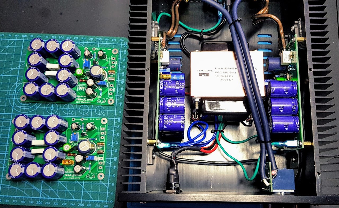
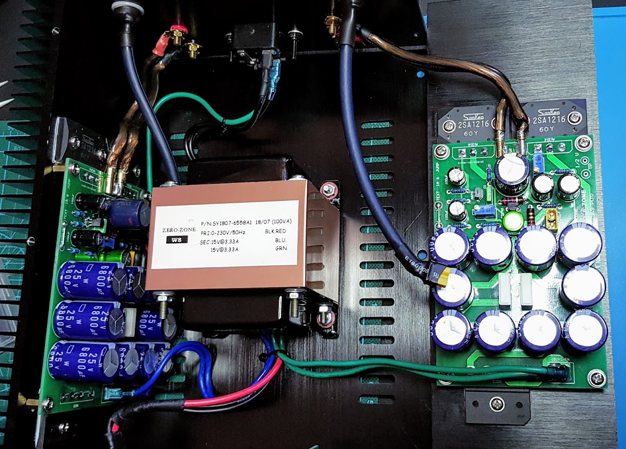
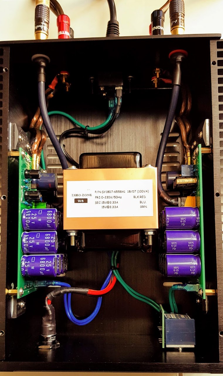
I still haven't inserted the new JLH 1969 in to the chassis... I'll do it this weekend.
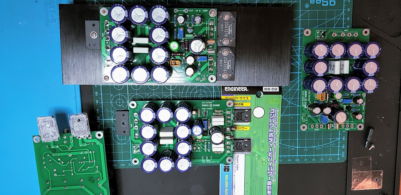
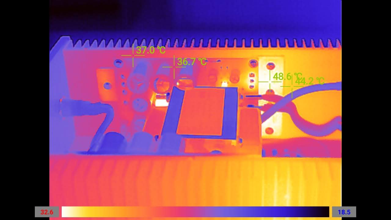
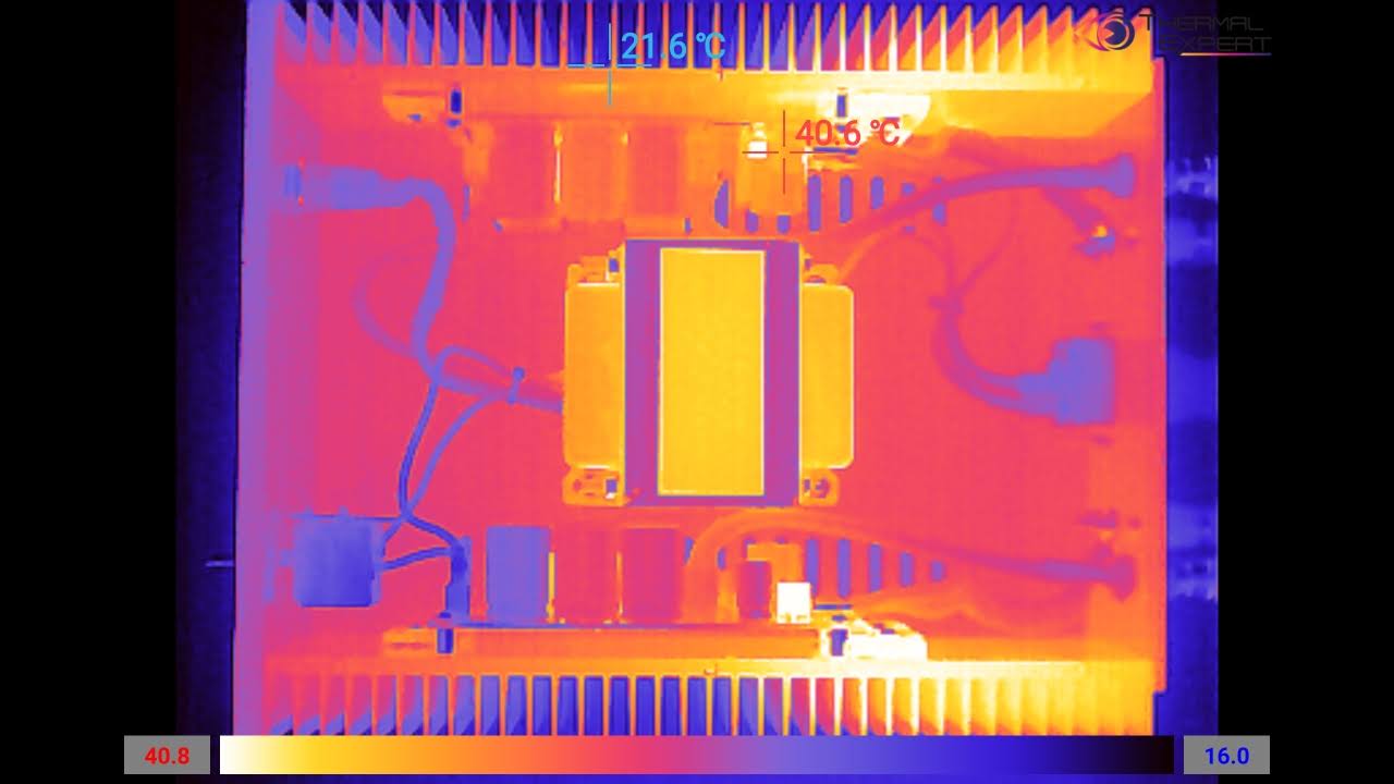
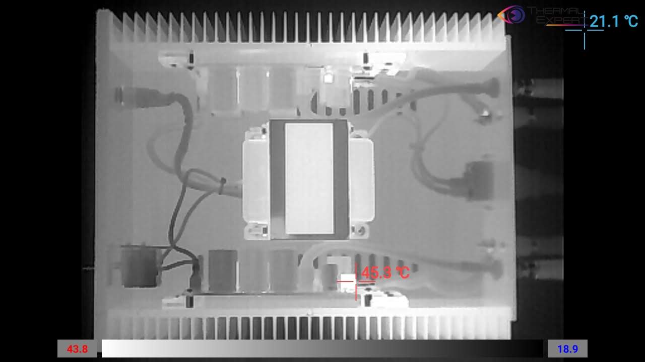
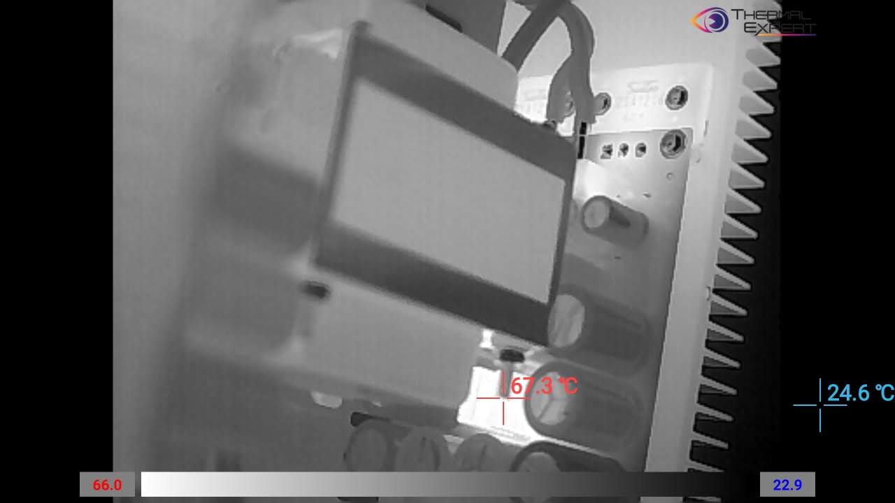
I finished the build today and alls not well.
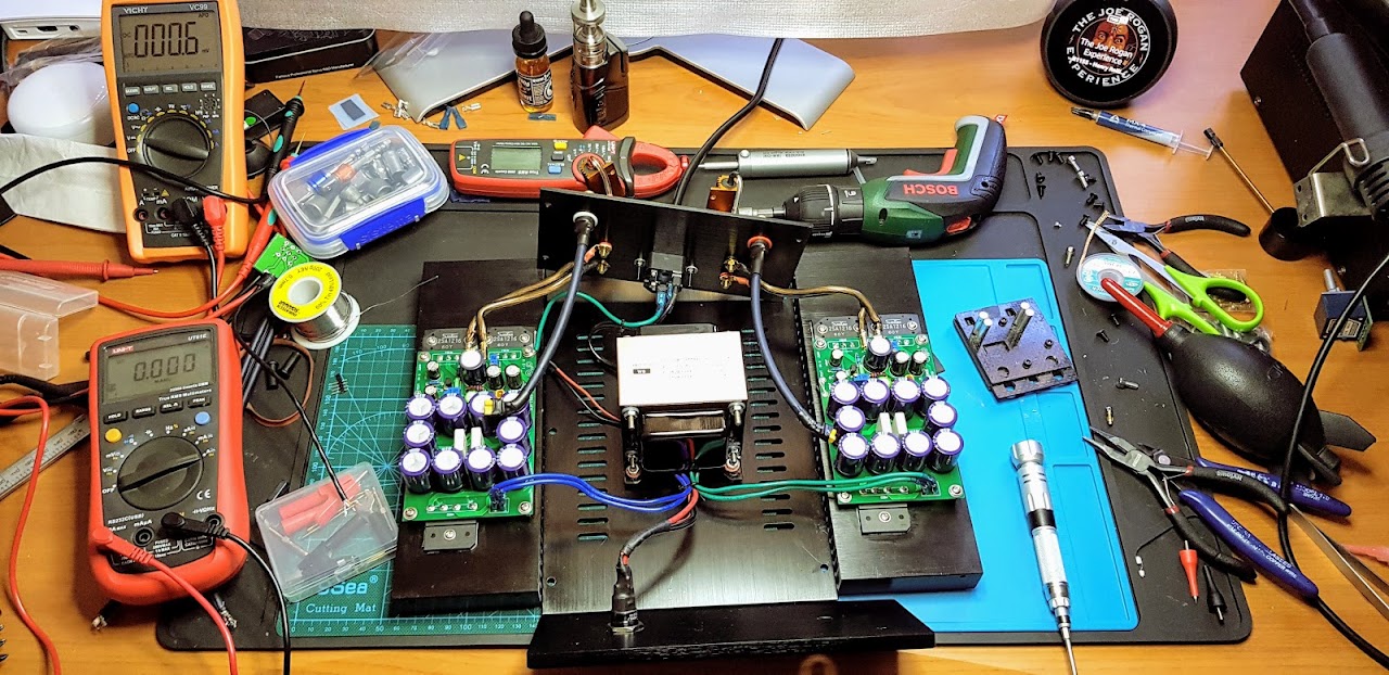
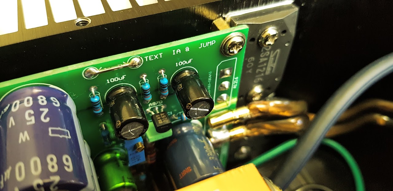
1.- I wasn't able to get 1/2 voltage, I measured 20.4v but the highest I could get the TP was 9.1v w/ "TEXT"at 1A. And this was after 1hr warm up. At cold TEXT is 0.950 and starts increasing.
2.- I left it as above and inserted it in to the chassis, and tested it.
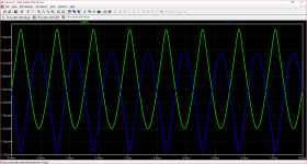
3.- It started off sound OK, but then started to sound wrong or distorted.
4.- Measured it again, and everything seemed OK.
5.- Audio test... worse the preamp is audible through the speakers w/ the amp off and it sound awful when on.
Now I'm lost how to debug... the ACA amp sounded really nice, this sounds broken and all I did was bypass the alps volume and use connectors instead of direct solder.
Pics...can you see anything wrong? How should I debug?
Last edited:
I did not understand anything you said.
I think you're confusing the 1/2 power settings and the bias setting.
moreover, from my point of view, a JLH, the more simple it is and the better it works.
1-very good PSU
2- the good transistors with the good gains and especially of origin certified.
I have never been able to burn a jlh, or to distort it and even less
to make it sound bad.
So, I think you got lost in debugging
I measured 1A between the "TEXT" points, then measured 20.4v between TEXT and out ground, then I tried to get TP to 10.2v, but the highest it would go is 9.1v.I did not understand anything you said.
I think you're confusing the 1/2 power settings and the bias setting.
- Home
- Amplifiers
- Solid State
- JLH 10 Watt class A amplifier