Aikido SLPS & Hybrid Headphone Amplifier
Here is a valve transistor hybrid that looks a bit like the JLH ( half way down the page ). It also has the bootstrap CCS. The simplicity of setting a current favours valves.
Here is a valve transistor hybrid that looks a bit like the JLH ( half way down the page ). It also has the bootstrap CCS. The simplicity of setting a current favours valves.
Class A -AB variation on JLH
Re some recent comments about dissipation of heat with JLH Class A circuits and personal experience with having built the 1969 and 1996 versions I can identify with this and with the bulk and the limited power output of the equipment.
The MC33078 op.amp a favourite of Nigel's uses an all NPN output stage to to avoid the dead band at crossover. This has been a fairly common strategy with op.amps for a couple of decades now.
To date I have not seen this used in a power amplifier which is presented with much lower impedance loads presented by amplifier inputs or headphones. There is still a limit on output current but it is possible to extract a little more than it needs for Class A running.
In this example I have kept the singleton input, a single supply rail and the split phase drive - I had no luck with making a stable version using a bootstrap collector load and had to use a Constant Current arrangement.
The aim is for 15W into 8R where the power consumption is about half that of my 1996 circuit. The circuit can be adapted for lower power.
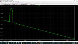
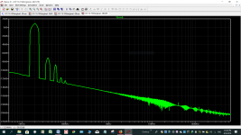
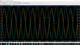
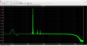
The attached images show FFT's at 1 Watt RMS output at 1kHz and 20 kHz and a display of peak currents at 15W - Q6 and Q7 are the NPN outputs and Q5 the supplementary driver.
If there is sufficient interest I will post the full circuit.
Re some recent comments about dissipation of heat with JLH Class A circuits and personal experience with having built the 1969 and 1996 versions I can identify with this and with the bulk and the limited power output of the equipment.
The MC33078 op.amp a favourite of Nigel's uses an all NPN output stage to to avoid the dead band at crossover. This has been a fairly common strategy with op.amps for a couple of decades now.
To date I have not seen this used in a power amplifier which is presented with much lower impedance loads presented by amplifier inputs or headphones. There is still a limit on output current but it is possible to extract a little more than it needs for Class A running.
In this example I have kept the singleton input, a single supply rail and the split phase drive - I had no luck with making a stable version using a bootstrap collector load and had to use a Constant Current arrangement.
The aim is for 15W into 8R where the power consumption is about half that of my 1996 circuit. The circuit can be adapted for lower power.
The attached images show FFT's at 1 Watt RMS output at 1kHz and 20 kHz and a display of peak currents at 15W - Q6 and Q7 are the NPN outputs and Q5 the supplementary driver.
If there is sufficient interest I will post the full circuit.
Attachments
"In this example I have kept the singleton input, a single supply rail and the split phase drive - I had no luck with making a stable version using a bootstrap collector load and had to use a Constant Current arrangement.
---
If there is sufficient interest I will post the full circuit."
Please !
---
If there is sufficient interest I will post the full circuit."
Please !
Soon - meantime some more simulation images."In this example I have kept the singleton input, a single supply rail and the split phase drive - I had no luck with making a stable version using a bootstrap collector load and had to use a Constant Current arrangement.
---
If there is sufficient interest I will post the full circuit."
Please !
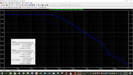
For comparisons with 10W JLH Class A the CCF IM plot is at this power output level. The stability margin is at close enough to 15 W both results into 8R.
Attachments
Dear Mjona,
Kindly open a new thread or continue in your thread Simple Class AB - Linsley-Hood 1970 if you feel it will be more appropriate there.
--Sarma.
Kindly open a new thread or continue in your thread Simple Class AB - Linsley-Hood 1970 if you feel it will be more appropriate there.
--Sarma.
Last edited:
Following this thread with interest. Want to ask how close is this board compared to the original JLH?
2pcs Atom BR Version NPN JLH1969 Single-ended Class A power amplifier bare PCB | eBay
I've seen it using both MT200 (2SA1216) and TO264 (can't see part) style output devices. I'm inclined towards 2SA1216 mainly because of the larger surface area for heatsinking.
2pcs Atom BR Version NPN JLH1969 Single-ended Class A power amplifier bare PCB | eBay
I've seen it using both MT200 (2SA1216) and TO264 (can't see part) style output devices. I'm inclined towards 2SA1216 mainly because of the larger surface area for heatsinking.
2pcs Atom BR Version NPN JLH1969 Single-ended Class A power amplifier bare PCB | eBay
I've seen it using both MT200 (2SA1216) and TO264 .
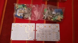
I assembled an amp with these pcb and they are very good and very small.
I mounted with sc5200 I had in reserve for years + BD139-16 + BC560C.
it works very well but not enough for me to keep it whole
this seller seems to have all the pcb of the market !!
They usually do. One or very few manufacturers make the boards etc and hundreds of sellers sell the same thing; hence a lot of sellers cannot provide support for their products because they're only selling and not manufacturing etc.
I'm sure you can study and rearrange the circuit board traces into a schematic for such a simple design, especially since the original schematic is widely published and the parts overlay on the PCB already shows the relevant component values and connection labels. When that PCB was first released as a kit, it came with MT200 transistors - but all transistors are opposite sex type and polarized caps and the power supply polarity is reversed, otherwise, it's identical to published schematics seen everywhere. However, now that the Sanken transistors are obsolete, I can think of much better uses for them in a quality class AB design, assuming they aren't actually fakes ")
Seriously, don't waste those precious Sanken Hifi transistors on little class A amplifiers when TIP36 or TIP2955 (TO247) will do fine and sound just as wonderful, if not better. You could also add short leads to TO3 style transistors like MJ2955, mounted to the 'sink directly or via a thick bracket. I do mean thick, like 4-6mm because typical extrusions of flimsy 2.5mm alumininium are useless at cooling constantly hot transistors, whether they have large or small backplates. It's the heatsink itself that needs the extra area since the transistors can transfer the heat just fine with mica rather than silicone rubber washers - just add plenty of thick metal to conduct the heat fast enough.
Seriously, don't waste those precious Sanken Hifi transistors on little class A amplifiers when TIP36 or TIP2955 (TO247) will do fine and sound just as wonderful, if not better. You could also add short leads to TO3 style transistors like MJ2955, mounted to the 'sink directly or via a thick bracket. I do mean thick, like 4-6mm because typical extrusions of flimsy 2.5mm alumininium are useless at cooling constantly hot transistors, whether they have large or small backplates. It's the heatsink itself that needs the extra area since the transistors can transfer the heat just fine with mica rather than silicone rubber washers - just add plenty of thick metal to conduct the heat fast enough.
Following this thread with interest. Want to ask how close is this board compared to the original JLH?
2pcs Atom BR Version NPN JLH1969 Single-ended Class A power amplifier bare PCB | eBay
I've seen it using both MT200 (2SA1216) and TO264 (can't see part) style output devices. I'm inclined towards 2SA1216 mainly because of the larger surface area for heatsinking.
The closest I can get to the original JLH is the revised version that was published in Wireless World in the December issue of 1970 on page 608.
This covered a number of other amendments including the constant current load, the power supply a phase-split circuit to bridge a pair of amplifiers and various options for the matching pre-amp.
I have re-worked my circuit to include the constant current load to match as per JLH's 1970 amendment.
The additional mods being proposed to the latter involve an additional transistor in each channel, a couple of signal diodes, and a few capacitors and resistors.
I have some electrical repairs to attend to in the morning. I will check my work and post my circuits later during the day. I see these as having more in common with the JLH Class A than his Class AB of 1970.
Last edited:
Hey thanks a lot Ian, this is great. I'm almost done with my class A headphone amp project plus some backlogs, but this JLH amp is quite interesting. The MJ2955 are cheap too.I'm sure you can study and rearrange the circuit board traces into a schematic for such a simple design, especially since the original schematic is widely published and the parts overlay on the PCB already shows the relevant component values and connection labels. When that PCB was first released as a kit, it came with MT200 transistors - but all transistors are opposite sex type and polarized caps and the power supply polarity is reversed, otherwise, it's identical to published schematics seen everywhere. However, now that the Sanken transistors are obsolete, I can think of much better uses for them in a quality class AB design, assuming they aren't actually fakes
Seriously, don't waste those precious Sanken Hifi transistors on little class A amplifiers when TIP36 or TIP2955 (TO247) will do fine and sound just as wonderful, if not better. You could also add short leads to TO3 style transistors like MJ2955, mounted to the 'sink directly or via a thick bracket. I do mean thick, like 4-6mm because typical extrusions of flimsy 2.5mm alumininium are useless at cooling constantly hot transistors, whether they have large or small backplates. It's the heatsink itself that needs the extra area since the transistors can transfer the heat just fine with mica rather than silicone rubber washers - just add plenty of thick metal to conduct the heat fast enough.
2 of these heatsinks for 2 channels.
HEAT SINK TO-3 1.2degC/W - 520AB1250MB(TO-3X2) (Fnl) | eBay
That'll be good. My speakers aren't too sensitive though, probably need sensitive ones for these 10W amps.
There's several JLH 1969 boards on the bay with 3 instead of 2 output transistors, haven't traced the circuit to see how close they are though.The closest I can get to the original JLH is the revised version that was published in Wireless World in the December issue of 1970 on page 608.
This covered a number of other amendments including the constant current load, the power supply a phase-split circuit to bridge a pair of amplifiers and various options for the matching pre-amp.
I have re-worked my circuit to include the constant current load to match as per JLH's 1970 amendment.
The additional mods being proposed to the latter involve an additional transistor in each channel, a couple of signal diodes, and a few capacitors and resistors.
I have some electrical repairs to attend to in the morning. I will check my work and post my circuits later during the day. I see these as having more in common with the JLH Class A than his Class AB of 1970.
for me, these are the kits that have always given the best result once the transistor changed and the capacitors for original models
ST2N3055 New Original JLH 1969 Deux Canaux Simple CLASSE Un Preampli Amplificateur de Puissance DIY kit Transistor Amplificateurs Conseil dans Amplificateur de Electronique sur AliExpress.com | Alibaba Group
ST2N3055 New Original JLH 1969 Deux Canaux Simple CLASSE Un Preampli Amplificateur de Puissance DIY kit Transistor Amplificateurs Conseil dans Amplificateur de Electronique sur AliExpress.com | Alibaba Group
My little circuit I showed was a very simple preamp in the spirit of the JLH. My big point was to consider making it's output very high and giving the JLH a gain of lests say 2. This would assume the use of an oscilloscope to be certain things are happy.
The green resistor I showed was a common tweak. It may or may not be a good idea, ears will say. The transistors I used should allow the NE5532 or MC33078 to work in class A as most lighly loaded op amps do. I think I tried LM358 ( LM324N ) with this same circuit and got good results! That was purely for fun.
The green resistor I showed was a common tweak. It may or may not be a good idea, ears will say. The transistors I used should allow the NE5532 or MC33078 to work in class A as most lighly loaded op amps do. I think I tried LM358 ( LM324N ) with this same circuit and got good results! That was purely for fun.
Yes, the real parts are hard to beat in this design. I have listened for some days to a ready built -ve polarity (MJ2955) version that was left with me to change back to original +ve polarity and 2N3055 transistors. I compared the channels in mono but it was hard to tell if there was any significant difference. I can say that I did enjoy the end result in stereo but of course, I could just be imagining it sounded better.
Even when idling, each channel has to dissipate approximately its power supply of 1.2A at the rail voltage - say 30V. That's 36W! The heatsink has to dissipate that as hot air, whilst staying within safe indoor temperature limitations. On a warm 25C day, the heatsink with 1.2C/W rating would reach 25+(36*1.2)C or 68C. That's a bit too hot and you need 2 of them. I think you should start with 2 heatsinks rated at around 0.5 - 0.8C/W each. Otherwise, the heatsinks would be painful to touch if allowed to exceed 55C. 60C is the highest you should contemplate and they should be protected by a guard mesh or rails of some kind. Note also that the heatsink fins must be aligned vertically to achieve their rating and that heatsink would have to be stood on end. You could also add fans but that is seldom practical or truly quiet enough.
Even when idling, each channel has to dissipate approximately its power supply of 1.2A at the rail voltage - say 30V. That's 36W! The heatsink has to dissipate that as hot air, whilst staying within safe indoor temperature limitations. On a warm 25C day, the heatsink with 1.2C/W rating would reach 25+(36*1.2)C or 68C. That's a bit too hot and you need 2 of them. I think you should start with 2 heatsinks rated at around 0.5 - 0.8C/W each. Otherwise, the heatsinks would be painful to touch if allowed to exceed 55C. 60C is the highest you should contemplate and they should be protected by a guard mesh or rails of some kind. Note also that the heatsink fins must be aligned vertically to achieve their rating and that heatsink would have to be stood on end. You could also add fans but that is seldom practical or truly quiet enough.
Last edited:
I dared not say it.
for my "big" jlh, I recycled a frame of cerwin vega A400 with two transistor
by heatsink, with 27vdc, I am at 1.5A (+/- 40w)
and it warms nicely.
on another I have a huge power supply heatsink for both transistor pair and in the summer I can not make it work long, it gets too hot.
for my "big" jlh, I recycled a frame of cerwin vega A400 with two transistor
by heatsink, with 27vdc, I am at 1.5A (+/- 40w)
and it warms nicely.
on another I have a huge power supply heatsink for both transistor pair and in the summer I can not make it work long, it gets too hot.
for me, these are the kits that have always given the best result once the transistor changed and the capacitors for original models
ST2N3055 New Original JLH 1969 Deux Canaux Simple CLASSE Un Preampli Amplificateur de Puissance DIY kit Transistor Amplificateurs Conseil dans Amplificateur de Electronique sur AliExpress.com | Alibaba Group
I have bought such a kit. Wanted to try it just out of curiositty. But, due to family issues I don't have the time now to build anything. But, one day I'll do it
Attachments
it's not quite the same, this one has bias potentiometers and voltage balancing.
mine (actually the simplest and cheapest) works with resistances that must be changed to adjust.
I have yours too and I still have it, it serves me the aboratory to try
to3 power transistor that I collect for years
mine (actually the simplest and cheapest) works with resistances that must be changed to adjust.
I have yours too and I still have it, it serves me the aboratory to try
to3 power transistor that I collect for years
- Home
- Amplifiers
- Solid State
- JLH 10 Watt class A amplifier