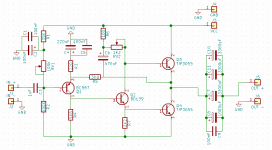
That rca amp is funny. What are trying to accomplish with these diodes in output?
Thermal tracking of the bias current in a circuit like this is not very good and bias current has a huge effect on THD below 1W. Note there is no adjustment of idle current and it will drift with changes in mains Voltage. The 1 Ohm resistors R13, R14 help minimize the change. The diodes reduce the losses when the amp is delivering power and R13 and R14's power requirement.
If the Eico Cortina ( RCA ) amp was built with modern transistors and biased class A it should work very well. Even in class AB it wasn't bad.An oscilloscope with spectrum analyzer a must. It's too easy to criticize an idea when in truth it was oscillation or crossover distortion to blame. This amp will most likely oscillate with modern devices.
If you do build an amp like this a regulated power supply would help. If using diode biasing keep them close to the outputs. I have a hunch 3 x 1N4007 and a very small value resistor would work to give circa 0.9 amp standing current. I imagine the amplifier would have a very open sound on vocals. A little bit of colour when loud. If the bias is hopelessly wandering it is often that the heat sink is too small. Although I am not a fan of switchmode power supplies one might do well for this idea.
If you do build an amp like this a regulated power supply would help. If using diode biasing keep them close to the outputs. I have a hunch 3 x 1N4007 and a very small value resistor would work to give circa 0.9 amp standing current. I imagine the amplifier would have a very open sound on vocals. A little bit of colour when loud. If the bias is hopelessly wandering it is often that the heat sink is too small. Although I am not a fan of switchmode power supplies one might do well for this idea.
I think we all who are reading this thread already know that very well ......
The diodes reduce the losses when the amp is delivering power and R13 and R14's power requirement.
...
Don't you think that the company had "other profitable motives" when suggesting a circuit like this one ... not hard to come to such conclusion when you run through a couple of realistically possible fault scenarios ...
My 2cents
hello Cerniu,
I would suggest you to join all all i/p side and NFB grounds together (by a plane) then run track to the star. I would also suggest you to keep an option of lifting this ground with a 10ohm resistor, that can be shorted by a jumper if resistor is not required/desired.
regards
prasi
edit:also 100nf bypass cap on the o/p is doing any useful job? i would use at least a 2.2u or parallel 2-3 such caps to get it to pass audio.
Last edited:
I think we all who are reading this thread already know that very well ...
Don't you think that the company had "other profitable motives" when suggesting a circuit like this one ... not hard to come to such conclusion when you run through a couple of realistically possible fault scenarios ...
My 2cents
The guy I quoted from post 4839 didn't understand the reason for the diodes, that's why he ask the question. There are many here that do not have the experience or education that some of us take for granted. Tech schools today don't spend much time on analog circuits. When members such as the one I quoted ask questions, they deserve a polite, concise answer and not to be made to feel like they are being talked down to.
That design was never intended for class A operation, just look at the rating of the transformer. And in case you can't find a listing on the output transistors, they are TO-66, Vceo=35V, Pt=29W. I think it was mentioned earlier that the design was from 1959 (post 4838). It looks more like mid to late 60's to me. In those days you would have been lucky to find 1 Ohm 1 Watt resistors in stock anywhere. Those 5W or 10W wire wound square ceramic resistors were not available. Special order at best if the manufacturer would even talk to you. Hard for a DIYer to do much with solid state in those days. (Note the JLH doesn't use low value emitter resistors.) I remember in 1969 it was still hard to find anything to use as emitter resistors. Allied Radio and Lafayette had nothing in their catalogs except these wire wound axials that looked like carbon comps and were rated at 2W. Best you could do was run two or three in parallel.
hello Cerniu,
I would suggest you to join all all i/p side and NFB grounds together (by a plane) then run track to the star. I would also suggest you to keep an option of lifting this ground with a 10ohm resistor, that can be shorted by a jumper if resistor is not required/desired.
regards
prasi
edit:also 100nf bypass cap on the o/p is doing any useful job? i would use at least a 2.2u or parallel 2-3 such caps to get it to pass audio.
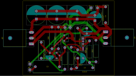
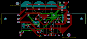
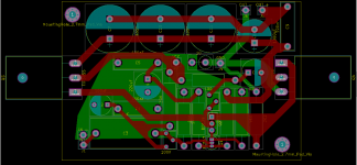
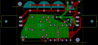
Not sure if I done it correctly but I modified version1 (both pictures are of the same pcb, but with emphasis on different pcb layers for better visibility) of the pcb acording to your suggestions. Could you elaborate what such a plane improves and what are the benefits of that 10ohm resistor.
As for the small cap on the output, I have moved it slightly so a bigger cap could be put there (though not MKP, atleast not any I have found).
Attachments
This example layout might give you some idea JLH 10 Watt class A amplifier
Trace the signal side ground from IN-, R2, C2 , NFB-C4, etc. I also used an optional resistor to lift this ground from Power ground (IGND-PGND).
The ground lift resistor is as per https://www.updatemydynaco.com/documents/GroundingProblemsRev1p4.pdf
and is generally accompanied by two antiparallel diodes. See the initial layout of honey badger posted by ostripper
This example layout might give you some idea JLH 10 Watt class A amplifier
Trace the signal side ground from IN-, R2, C2 , NFB-C4, etc. I also used an optional resistor to lift this ground from Power ground (IGND-PGND).
The ground lift resistor is as per https://www.updatemydynaco.com/documents/GroundingProblemsRev1p4.pdf
and is generally accompanied by two antiparallel diodes. See the initial layout of honey badger posted by ostripper
Thank you. So I have done the signal ground plane right?
Also, I see you use 2SA970 on the input, would it be an improvement over BC559 or its negligible?
Why not read JLH's own commentaries on the design and component choices? Start with the original article - there are more, spaced over 30 odd years but little has required changing since the beginning. The Class-A Amplifier Site
BC559 C appears to be a very good one.
Because it was mentioned 2SA970 in the JLH2003 update documentation, I used 2SA970.
Layout:
What is meant was
1. keep all the signal traces short
2. connect their grounds with a common plane
3. This area (area covered by signal traces and their grounds) should be as compact as possible. Although it is not always possible due to mechanical constraints of PCB mounting and general chassis layout, etc.
4. run a trace from this ground to PGND with an optional lift resistor
However there are different views and best is to build one and test.
regards
Prasi
2SA970 is a nice device. Not really better. I would imagine BC560C to be ideal. The problem with 2SA970 is I read about fakes. BC327-40 is more likely to be genuine. The noise of the 327 is 0.6 nV/root Hz which is as low as any. The 100K mid point setting resistors will not be ideal for noise. 2SA1085 is another option.
2N4403 was used in the past. It isn't really a hi fi device. As it was usually used in a feedback circuit like the JLH it worked OK. Often used with a 741( or 2N4401 ) to make a microphone preamp. Said to be far better than would be thought. A resistor taken to th -ve rail to force the 741 into class A.
2N4403 was used in the past. It isn't really a hi fi device. As it was usually used in a feedback circuit like the JLH it worked OK. Often used with a 741( or 2N4401 ) to make a microphone preamp. Said to be far better than would be thought. A resistor taken to th -ve rail to force the 741 into class A.
With very simple designs like the JLH, noise isn't governed just by the type of input transistor. In a series of three builds some years ago, some friends built their versions with different input transistors including KSA992, BC560C and original 2N3906. There were more comparisons that I heard about but didn't see the figures. You could not see any clear difference between these 3 on a 'scope. Soundcard measurements showed that the version with 2N3906 had slightly higher noise by about 2dB but you couldn't hear that as being any different. I think all parts were sourced from (then) Fairchild Semiconductuctor and I suspect there were common manufacturing processes used which influenced the resulting numbers.
My suggestion is to build it with the original part or use whatever low level amplifier transistor you have on hand (BC559, BC214 are old favourites that would be fine too). This isn't a high tech, high gain or SOTA design so don't sweat it. Listen to the sound quality first and then think about what could be improved in some degree. In my case, noise was never an issue with my last build because it has the alternative capacitance multiplier filtered power supply shown in the original article. This changes the game a little more than parts swaps, at the cost of more heat
My suggestion is to build it with the original part or use whatever low level amplifier transistor you have on hand (BC559, BC214 are old favourites that would be fine too). This isn't a high tech, high gain or SOTA design so don't sweat it. Listen to the sound quality first and then think about what could be improved in some degree. In my case, noise was never an issue with my last build because it has the alternative capacitance multiplier filtered power supply shown in the original article. This changes the game a little more than parts swaps, at the cost of more heat
Hello Ian,
Could you let me know if the ESP Cap MX is a suitable one for the project? Fig. 3 of Capacitance Multiplier Power Supply Filter (for the JLH2003).
I have the Juma Cap MX with Mosfet but I am looking for cooler options.
regards
Prasi
Could you let me know if the ESP Cap MX is a suitable one for the project? Fig. 3 of Capacitance Multiplier Power Supply Filter (for the JLH2003).
I have the Juma Cap MX with Mosfet but I am looking for cooler options.
regards
Prasi
I could imagine if enough care was taken noise could be reduced. Source noise also counts. If you run the amp with various resistors to minic a volume control you will get different noise. As the upper resistance is 100K it will be dominant. If the circuit was using 10K + 10K ( 5K ) it might be OK. Naturally hum might increase so the decoupling will need to change. There is a theory that noise is colouration. Equally with class AB it can slightly help the low level distortion as dither of sorts.
Many of my friends who design electronics will argue in favour of low noise transistors for sound quality regardless of circuit. They also point out how easy it is to damage them. If testing them be sure they are the right way in the tester. I doubt it should matter, all the same.
MPS92 is a good device for all needs and the MPSA94 ( usually by different codings like KSA now ) is a wonder device.
Hi Prasi
The final forms of both JLH's and Rod Elliott's cap multipliers are both Darlington topology so they will have similar losses. The voltage drop across the multiplier circuit (and hence dissipation) is higher than for the simple, one transistor form of Rod's, shown as fig.1. That might be an optimal arrangement but unfortunately, lower transistor gain translates to less effective noise rejection.
I'm no expert with analysis but the performance of his final fig.4 design will obviously be the best as it has plenty of passive filtering too.
Ideally, you could use a suitable high gain, single power BJT that has sustained beta up to about 3A. It still wouldn't perform as well overall as a Darlington but the efficiency would be optimal for lowest power loss, cooler operation and would probably be quite good enough for the JLH class A, as long as the other passive filtering was in place. Rod's application was for the DOZ amplifier which runs a bit harder with more power than the standard JLH so I guess that would be tougher application with considerably more heat to dispose of in any case.
I also wondered about a linear LDO IC regulator as a cap multiplier. I doubt that many have a sufficient current rating but they can't be too bad in the role if they can cope with highly capacitive loads
One of my "must do one day" projects is a choke input supply for the JLH which, theoretically, should provide much lower noise and/or hum than most of the "conventional" approaches.
Part of that process would be to simulate the effects of changing the apparent power supply impedence (vs frequency) and see what effect that has on noise transfer into the amp.
Totally "armchair" at the moment, and likely to stay that way for a while due to other demands on my time.
Part of that process would be to simulate the effects of changing the apparent power supply impedence (vs frequency) and see what effect that has on noise transfer into the amp.
Totally "armchair" at the moment, and likely to stay that way for a while due to other demands on my time.
Hi Prasi
The final forms of both JLH's and Rod Elliott's cap multipliers are both Darlington topology so they will have similar losses. The voltage drop across the multiplier circuit (and hence dissipation) is higher than for the simple, one transistor form of Rod's, shown as fig.1. That might be an optimal arrangement but unfortunately, lower transistor gain translates to less effective noise rejection.
I'm no expert with analysis but the performance of his final fig.4 design will obviously be the best as it has plenty of passive filtering too.
Ideally, you could use a suitable high gain, single power BJT that has sustained beta up to about 3A. It still wouldn't perform as well overall as a Darlington but the efficiency would be optimal for lowest power loss, cooler operation and would probably be quite good enough for the JLH class A, as long as the other passive filtering was in place. Rod's application was for the DOZ amplifier which runs a bit harder with more power than the standard JLH so I guess that would be tougher application with considerably more heat to dispose of in any case.
I also wondered about a linear LDO IC regulator as a cap multiplier. I doubt that many have a sufficient current rating but they can't be too bad in the role if they can cope with highly capacitive loads
Thanks Ian for you explanation.
regards
Prasi
I think I read in this application a Darlington will not work as well as predicted because one transistor hogs the workload, if I remember due to Early effect. Other people show a cascade working better. I used a complimentary feedback pair with good results.
http://sound.whsites.net/p15_fig4.gif
http://sound.whsites.net/p15_fig4.gif
- Home
- Amplifiers
- Solid State
- JLH 10 Watt class A amplifier