I think it should be OK "as is" though.
Thanks - I have had a play with larger R values without any adverse effect. Good to know.
In the original article, altering (raising) R1 and R2 will lower the quiescent current.
Got it - ta.
To arrive at some values for these resistors we need to know your actual supply voltage.
5V supply gives an output of +/-2V PP into a 4 Ohm speaker
9V supply gives an output of +/-3V PP into a 4 Ohm speaker
15V supply gives an output of +/-6V PP into a 4 Ohm speaker
…or do I need to calculate/supply the current draw at each of those supply's as well?
Thanks.
I think you might find the loudspeaker power equation useful: P = (Vpp)^2 / 8 RL.
So your 1st case of +\- 2V PP into 4 ohms becomes: P = 4^2 / (8 x 4) = 16 / 32 = 0.5W (assuming +\-2V PP means 4Vpp).
Similarly at 15v you get +\-6V PP giving P = 12^2 / (8 x 4) = 4.5W - that is 3 times the voltage (and 3 times the current) gives 9 times the power as expected.
If nothing else it confirms your readings as correct.
Thanks - I have had a play with larger R values without any adverse effect. Good to know.
Got it - ta.
5V supply gives an output of +/-2V PP into a 4 Ohm speaker
9V supply gives an output of +/-3V PP into a 4 Ohm speaker
15V supply gives an output of +/-6V PP into a 4 Ohm speaker
…or do I need to calculate/supply the current draw at each of those supply's as well?
Thanks.
Well you need to determine what you are aiming for. On 9 volts (in simulation) I can get almost (unbelievably) 8 volts pk/pk into 4 ohms.
Attachments
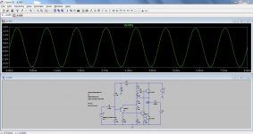
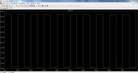
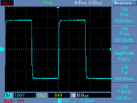
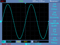
The attached screenshot shows an input of a 1V PP 100Hz square wave into the JLH69 config (with a bit more gain). It reproduces a 1V PP sine wave input very well.
My understanding is that this square wave 'ramping' is caused by the output AC coupling? I've tried some very big caps on the output (up to 10,000uF) and it doesn't seem to make a huge amount of difference.
So - a) is this a problem that needs to be solved or (can be) improved and b) if so - how do I approach that?
Thanks.
Attachments
What supply voltage are you running it at.
27V as per the JLH69. Yes, it was letting the sine wave through but it's clipping the square wave. Even if I drop R3 (on the original schem) back to 2.7K - it gets rid of the clipping but the 'ramping' is still there - same on the 5V version I'm working on as well.
Attachments
27V as per the JLH69. Yes, it was letting the sine wave through but it's clipping the square wave. Even if I drop R3 (on the original schem) back to 2.7K - it gets rid of the clipping but the 'ramping' is still there - same on the 5V version I'm working on as well.
This is LF roll-off.
Member
Joined 2009
Paid Member
Yes- all caps. In post #2884 Mooly shows a circuit of the JLH. In that circuit, C1 (bootstrap); C2 (feedback decoupler) are likely candidates needing to be increased, the input capacitor is next in line as well as the output capacitor. If your output cap did not make much difference try the others.
Member
Joined 2009
Paid Member
Minimizing capacitor distortion in electrolytics means minimizing the a.c. voltage across them - which means using large values where the corner frequency is well below the audio range. So if you want to make a high-pass filter to cut off the bass then you want to do it where you need only a small valued capacitor and therefore where it is economical to avoid using an electrolytic. The input cap is usually where this happens. My gosh, does that mean I agree with AndrewT 
I have question about measuring the current draw on this amp (JLH '69).
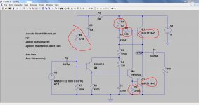
I understand that on a Class A topology the current draw varies with signal output and I can verify that in simulation - but I'm trying to get either an 'average' or 'peak' rating in mA based on a given input (1V PP Sine).
My aim is to start with building a low power (5V supply), low wattage (1/2 Watt), version to run off a wall wart - but I need to know approx. how much current the wart will need to supply.
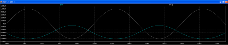
The attached sims show:
With input:
I[V2] - Current across 5V power supply = -510mA to +56mA
I[R7] - Current across 4R speaker = -510mA to +500mA
With no input:
I[V2] - Approx. -315mA
I[R7] - Approx. 0mA
I'd appreciate any advice on this.
I understand that on a Class A topology the current draw varies with signal output and I can verify that in simulation - but I'm trying to get either an 'average' or 'peak' rating in mA based on a given input (1V PP Sine).
My aim is to start with building a low power (5V supply), low wattage (1/2 Watt), version to run off a wall wart - but I need to know approx. how much current the wart will need to supply.
The attached sims show:
With input:
I[V2] - Current across 5V power supply = -510mA to +56mA
I[R7] - Current across 4R speaker = -510mA to +500mA
With no input:
I[V2] - Approx. -315mA
I[R7] - Approx. 0mA
I'd appreciate any advice on this.
Attachments
I have question about measuring the current draw on this amp (JLH '69).
I understand that on a Class A topology the current draw varies with signal output and I can verify that in simulation - but I'm trying to get either an 'average' or 'peak' rating in mA based on a given input (1V PP Sine).
My aim is to start with building a low power (5V supply), low wattage (1/2 Watt), version to run off a wall wart - but I need to know approx. how much current the wart will need to supply.
The attached sims show:
With input:
I[V2] - Current across 5V power supply = -510mA to +56mA
I[R7] - Current across 4R speaker = -510mA to +500mA
With no input:
I[V2] - Approx. -315mA
I[R7] - Approx. 0mA
I'd appreciate any advice on this.
You say you have little experience so please excuse me if try to clarify a few things.
Actually in class A amps the current from the power supply varies substantially less with the signal than in class AB designs.
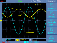
PMA's scope shot, I think, shows the current variation in the lower o/p transistor which is pretty much the inverse of the change in the o/p current but the change of the actual power supply current will be substantially less than this.
In theory it is possible that the supply current in class A amps does not change at all when a signal is applied but in practice it will usually change to some extent and in this design the action of the bootstrap capacitor does create some useful o/p current change with signal. ( in the upper o/p transistor ).
Usually we express the measurement of voltage, "V" across a component and current, "I" through a component.
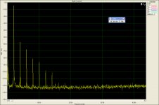
When john linsley hood developed this circuit in 1969 he was very happy to achieve total harmonic distortion levels of below 0.1% up until onset of clipping. By today's standards this is quite high but because the distortion is dominated by low order harmonics and because the amp is stable without compensation - the subjective sound is good.
However the distortion levels will be higher if you reduce the standing current in the o/p circuit and if you reduce the standing current a lot the distortion levels will be much higher.
Just wanted to mention that - some people don't mind the sound of higher distortion amps - like valve amps - if everything else is done well - but to achieve the levels of distortion same JLH specifies you will need high standing currents in the o/p stage.
I think PMA knows far more about this both objectively & subjectively than I do but I doubt if we will get him to give any subjective comments ? ? ?
Hope some of this is helpful
mike
Last edited:
In addition there is at least one more good reason to have a high standing current in the o/p stage of this amp design.
At some points of a real loudspeaker's motion with real music signals there can be quite substantial dips in loudspeaker impedance. At these times the amplifier will need to supply extra current to "control" the speaker cone movement.
With this design the current available to the loudspeaker is limited to just over 2 x times the standing current. In amplifiers with follower o/p stages this restriction is not present.
With larger speakers this may sound as if the amp does not have much of a "grip" over the speaker.
If you experiment with lower standing currents initially - you may find that the amp will be happier with smaller or more efficient speakers.
Good Luck
mike
Mike,
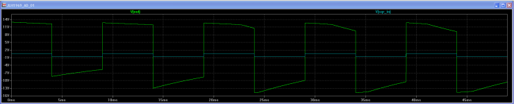
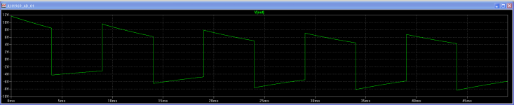
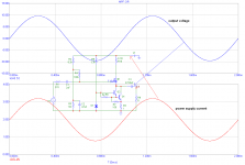
DIY beginners are very often intentionally cheated and fooled about function of certain circuits, I am sure it is a marketing tool of certain persons. Even SE class A does not draw a constant current from the power supply, please check the attached plots. It is a sum of idle current + signal (load) current. JLH is specific, its idle current is modulated by the signal.
DIY beginners are very often intentionally cheated and fooled about function of certain circuits, I am sure it is a marketing tool of certain persons. Even SE class A does not draw a constant current from the power supply, please check the attached plots. It is a sum of idle current + signal (load) current. JLH is specific, its idle current is modulated by the signal.
Attachments
Agreed, but although I never tried it - I think you could attempt a class A design with some kind of a CCS in the "upper" o/p transistor position - which in theory could draw a reasonably constant current from the PSU regardless of signal ? ? ?
Either way my main point was that the change of current drawn from the PSU in a class A amps is less than that of a class AB amps
mike
Either way my main point was that the change of current drawn from the PSU in a class A amps is less than that of a class AB amps
mike
- Home
- Amplifiers
- Solid State
- JLH 10 Watt class A amplifier