Hi everyone!
I bought a TX-DS777 and it seems to be stuck in standby.
When connected to mains the red stand-by led lights but when pushing the stand-by button nothing happens.
It turned on some times only yesterday after a month or more standing disconnected apart.
Using the service manual I followed the main signals and so far I found these:
- the secondary supply that keeps the microcontroller and some other logics on seems to be ok
- the standby button makes the voltage level to toggle and it seems to arrive on the main board (wirings ok)
- on the mains relay nothing arrives when I push the standby button
According to the fact that I saw it turning on I believe that it is something related to a voltage sensing or similar.
Is there some kind of memory backup that can be reset?
It is also not possible to access the service menu.
Any suggestion is really appreciated!
Thank you!
Last edited:
Next step, check for presence of full relay coil supply voltage. Usually it is applied to one end of the coil, the other end is then pulled to ground via the relay driver circuit. If the driver circuit is doing nothing, check its input. Sometimes you find a bad transistor in there. Generally keep an eye on bad solder joints around the relay, relay driver and its power supply.
Next step, check for presence of full relay coil supply voltage. Usually it is applied to one end of the coil, the other end is then pulled to ground via the relay driver circuit. If the driver circuit is doing nothing, check its input. Sometimes you find a bad transistor in there. Generally keep an eye on bad solder joints around the relay, relay driver and its power supply.
Hi!
I checked for a voltage level toggling on the base of the transistor that powers the relay coil but there was nothing. I suspect that it is the microcontroller itself that doesn't send the command for some reason...
Then you'll have to trace back this signal. Either it gets lost or the µC really does nothing.
If the µC is playing dead, it might just be crashing or not even starting up because of a flaky supply. You don't necessarily see that on a multimeter - and then you look at it on a scope and spot all kinds of nastiness or even an oscillating regulator. Dead electrolytics are a likely cause.
If the µC is playing dead, it might just be crashing or not even starting up because of a flaky supply. You don't necessarily see that on a multimeter - and then you look at it on a scope and spot all kinds of nastiness or even an oscillating regulator. Dead electrolytics are a likely cause.
Strange thing is that it turned on for few times just yestarday, so something moves!
Unfortuantely the microcontroller is on the bottom side of the main PCB so it is a pain to reach the pins. I will check again the supplies.
I was also wondering to feed the amp with more than 230V (not over 240V) with a variable transfomer to check what you are suggesting.
Unfortuantely the microcontroller is on the bottom side of the main PCB so it is a pain to reach the pins. I will check again the supplies.
I was also wondering to feed the amp with more than 230V (not over 240V) with a variable transfomer to check what you are suggesting.
sgrossklass, thank you for the hint!
Ok, I made further tests and found that the power supply that keeps the +13V for the standby suffered a big 50Hz ripple of 500-600mVpp.
According to the schematic, there is a limiting resistor that feeds the +5.6V LDO to the microcontroller (through a diode, so to obtain 5V) and other circuitry that goes to the microcontroller.
I tried to add a 1000uF capacitor after this resistor and magically the amplifier turned on. I believe that the LDO (a NJM78M56) was unable to manage that ripple...
Now is working ok but I believe that this is a workaround, not a fix.
With the capacitor the ripple after the resistor went similar to a sine (previously was almost triangular, you now, shark fin shaped) and remained of 200mVpp.
I hope that the LDO can manage it...
sgrossklass, thank you for the hint!
Ok, I made further tests and found that the power supply that keeps the +13V for the standby suffered a big 50Hz ripple of 500-600mVpp.
According to the schematic, there is a limiting resistor that feeds the +5.6V LDO to the microcontroller (through a diode, so to obtain 5V) and other circuitry that goes to the microcontroller.
I tried to add a 1000uF capacitor after this resistor and magically the amplifier turned on. I believe that the LDO (a NJM78M56) was unable to manage that ripple...
Now is working ok but I believe that this is a workaround, not a fix.
With the capacitor the ripple after the resistor went similar to a sine (previously was almost triangular, you now, shark fin shaped) and remained of 200mVpp.
I hope that the LDO can manage it...
Is there a big dropper capacitor on the primary mains side for the standby circuit? Replace that if so. Take some pics.
After some days it started again to remain in standby.
I will attach some screenshot of the service manual with the analisys.
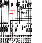
When the amplifier is in standby the following circuit supplies the microcontroller and some other circuitry:
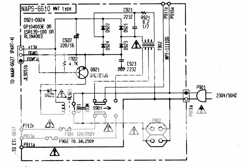
On another board there are the LDOs:
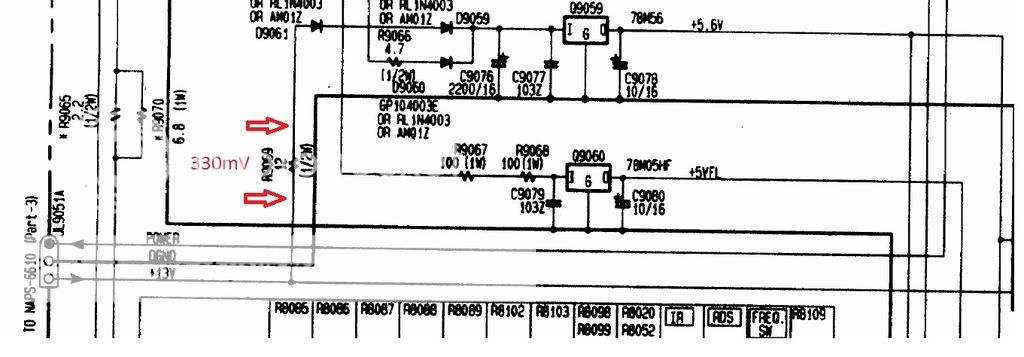
On the +13V rail (that stands at 15V with 233V on mains) there was the high ripple I told before.
I tried to add a 1000uF capacitor after R9069. With this mod the ripple that was 200mV become 30-50mV and the amplifier started.
After some days it stopped so I tried to change C922 with another 1000uF but with no change at all.
The ripple on the +13V rail is 200mVpp.
The voltage drop on R9069 is 330mV so I suppose a normal current.
Maybe there is something malfunctioning on the other circuit:
but I can't figure out what.
The high ripple that is still present on the 13V rail make me think that there is an unusual current drain on the other circuitry but there is nothing overheating or similar. Even the little transformer is rather warm but nothing strange.
Any suggestion?
I will attach some screenshot of the service manual with the analisys.
When the amplifier is in standby the following circuit supplies the microcontroller and some other circuitry:

On another board there are the LDOs:

On the +13V rail (that stands at 15V with 233V on mains) there was the high ripple I told before.
I tried to add a 1000uF capacitor after R9069. With this mod the ripple that was 200mV become 30-50mV and the amplifier started.
After some days it stopped so I tried to change C922 with another 1000uF but with no change at all.
The ripple on the +13V rail is 200mVpp.
The voltage drop on R9069 is 330mV so I suppose a normal current.
Maybe there is something malfunctioning on the other circuit:

but I can't figure out what.
The high ripple that is still present on the 13V rail make me think that there is an unusual current drain on the other circuitry but there is nothing overheating or similar. Even the little transformer is rather warm but nothing strange.
Any suggestion?

If it isn't any voltage here,check if another transistor or a resistor is between microcon. and Q921.
If a transistor check the transistor.If a resistor,disconnect and measure for voltage.
If nothing is, desolder Q901 and measure again,or heat the Q901 .
Are you sure that protection circuit does not affect the same circuit?
If a transistor check the transistor.If a resistor,disconnect and measure for voltage.
If nothing is, desolder Q901 and measure again,or heat the Q901 .
Are you sure that protection circuit does not affect the same circuit?
Attachments
Power on, comes from Q8003,PIN 63.
Shematic diagram 4. NAAR 6627.
Are the stand by voltages ok near or direct on microp.pins?
Unfortunately we don't know what the microprocessor takes in account to permit the on.
Do you see the micropr, what the case still?
Are TQFP32? See for bad solder points or any type of missing connections from pin 63 up to the base of Q921
Good luck!
Attachments
Last edited:
Hi thimios!
I already took measurements on the BJT that enables the relay, but there was no command coming from the microcontroller.
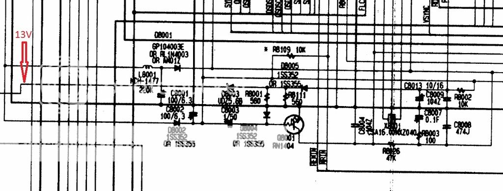
I assume that messing around the 13V / 5.6V produced some effect since the amplifier worked for a week and I believe that something is out of specification in the following schematic:
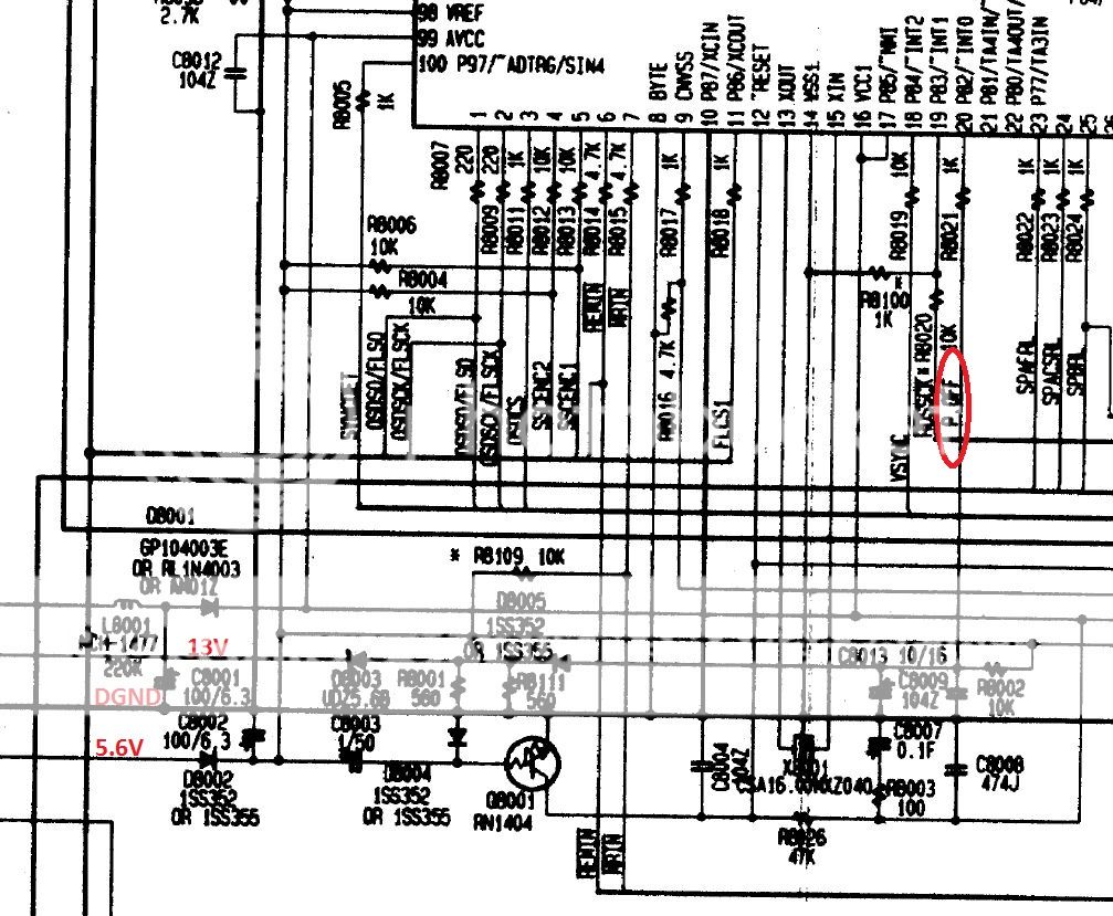
On that circuitry come unregulated 13V and regulated 5.6V. I highlighted the connection that goes to an interrupt pin of the microcontroller that has a suspicious label "power-off".
Unfortunately all the components that starts with "8" on the refdes are mounted on the bottom side and I have not managed to take all the PCBs out of the chassis...
I will try to figure out what the ucontroller expects on that "power-off"pin...
Any idea?
I already took measurements on the BJT that enables the relay, but there was no command coming from the microcontroller.
I assume that messing around the 13V / 5.6V produced some effect since the amplifier worked for a week and I believe that something is out of specification in the following schematic:

On that circuitry come unregulated 13V and regulated 5.6V. I highlighted the connection that goes to an interrupt pin of the microcontroller that has a suspicious label "power-off".
Unfortunately all the components that starts with "8" on the refdes are mounted on the bottom side and I have not managed to take all the PCBs out of the chassis...
I will try to figure out what the ucontroller expects on that "power-off"pin...
Any idea?
After few days of stop debugging, I unmounted the boards, this is what I found on the solder side of the main PCB:
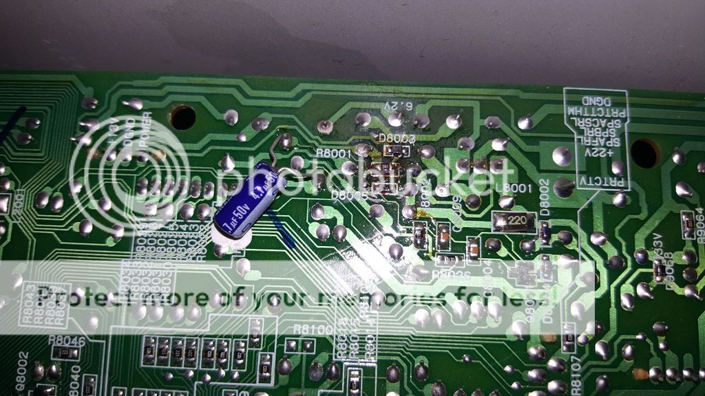
It seems that someone already reworked it.
I will try replacing diodes and zener and see if something moves.
I'm not going for now to turn it on while disassembled to avoid shorts and other issues...

It seems that someone already reworked it.
I will try replacing diodes and zener and see if something moves.
I'm not going for now to turn it on while disassembled to avoid shorts and other issues...
- Status
- This old topic is closed. If you want to reopen this topic, contact a moderator using the "Report Post" button.
- Home
- Amplifiers
- Solid State
- Onkyo TX-DS777 remains in stand-by