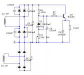
I have just 'upgraded' my preamp with another power supply. It was a 7x15 voltage doubler circuit. After I read the reviews at TNT audio I decided to build a zener regulated emitter follower for which I used the following circuit. Note: both sides are the same.
I use a 30 VA dual 15V non center tapped transformer. Each winding is used for a bridge as shown. I don’t have a earthed power outlet. I connected the case to the circuitground through a 150 ohms resistor.
My problem is that I can't get the grounding right. With the voltage doubler I didn't have a problem with this, but now I do. There is a small buzzing to be heard, which disappears when I touch a ground point of my circuit.
Does anyone have a solution to solve this problem? Would it be better to use a voltage doubler configuration with both windings in parallel? How can I measure if I can use my torroid with both windings in parallel?
I know it would be better to use a center tapped torroid, but it would be more convenient to just use this one.
Besides the grounding problems the supply is working very fine. I don’t have nasty turn on thumps anymore and the rails are adjustable to set the voltage very precisely.
Any ideas and comments are welcome.
Cheers,
Attachments
Hi!
You are pointing out that both sides are identical.
Does this mean complementary or really identical?
If they are not complementary, but identically, then you would have to
connect pos & neg supply different from what you have shown.
If both supply sides are the same, then you would have to connect
the pos end of the second supply to the negative end of the first
supply INSTAED of the connection behind the diode bridges.
(simple series connection of two independent voltage sources)
Cheers
Markus
two further points:
-Your schematic shows a NPN, but the letters say BD140.
BD 140 is a NPN.
-Your schematic does not show protection diodes.
Diodes across the outputs and freewheeling diodes across
the collector-emitter of the transistors might improve ruggedness.
Polarity of the diodes would be that under normal operating conditions,
they are non conductive.
Hope you are getting rid of your noise.
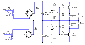
Chocoholic, thank you for your replies. I have attached a new diagram, showing both sides. I know the protection diodes are advisable, but don't improve the noise characteristics, if I'm correct.
"..then you would have to connect
the pos end of the second supply to the negative end of the first
supply INSTAED of the connection behind the diode bridges..."
What do you mean by saying instead of the connection behind the diode bridges?
Cheers,
"..then you would have to connect
the pos end of the second supply to the negative end of the first
supply INSTAED of the connection behind the diode bridges..."
What do you mean by saying instead of the connection behind the diode bridges?
Cheers,
Attachments
OK, you are doing it complementary. I think your connetcions
are fine. Also BC140 is right (NPN). First I thought BD140......
Another possibility would have been to set up two times
independend supplies, both with NPN transistor and simply
connect their outputs in series. This was what I suspected,
when you stated "identical"...
But your complimentary set up should be fine.
Your buzzing noise:
First I thought that you might have a unfortunate ground structure, but then the noise would not disappear simply by touching
any ground point.
It looks more like you have some parasitic effects, may be
capacitive couplings in the transformer.
Without the possibility to put a small capacitor from
your ground to earth or direct connection, you might try some of the follwing proposals.
-Polarity of the secondary windings. In principal there are
4 equivalent connections.
a) first primary and second primary in phase with mains.
b) first primary in phase, second in opposite direction.
c) first primary in opposite direction, second in phase.
d) both in opposite direction.
From first approach all these connections should be fine, because
we are dealing with isolated 50Hz voltages, which will be rectified
afterwards. But the capacitive couplings inbetween the windings
and towards mains are different. Also inductive impact from one winding to the next may be different, as every transformer has leakage fields.
-You may also connect your two transformer secondaries in series
and use it as a center tapped transformer with just one rectifier bridge.
I feel you will have to go through some trial and error.
Bye
Markus
Another idea:
You could try 5....10 Ohms in series of each secondary winding
of your transformer. Should be 1W types at least, better 2W...
depending on the current consumption of your amp.
The 10 Ohms will reduce the current peaks (through secondaries,
rectifier and C6 & C8), which might also be the reason for your
issues.
......
LaZarus said:I connected the case to the circuitground through a 150 ohms resistor.
My problem is that I can't get the grounding right. With the voltage doubler I didn't have a problem with this, but now I do. There is a small buzzing to be heard, which disappears when I touch a ground point of my circuit.
I'm not sure why you connected the case to the circuit ground with a resistor instead of just directly. It would be very easy to short out that resistor and see what happens to your noise.
If that doesn't help, I think you need to re-wire your transformer. Instead of using the winding separately, each with a separate bridge rectifier, try connecting them in series to make your own center-tap. Then connect the center tap to signal ground directly (instead of through the bridges as you currently do). Then you will only need one bridge rectifier for everything.
Good luck!
Then you will only need one bridge rectifier for everything.
Yes, but it sounds a lot better with two rectifiers. I don't think there is anything wrong with the circuit diagram; it's the physical implementation of the grounding which is probably wrong.
Thank you all for your help! It took some experimenting, but now I have a result I can live with for the time being.
It didn't had to do with my transormer. I checked with al your proposals. The 10 ohm resistor on the secondaries made the problem worse. The solution was to add two 330 ohms resistors after the main smoothing caps. The buzzing was now almost completely gone.
Charles, It is common practise to connect the chassis ground to the circuit grount through a 100 ohms resistor and a 100nF cap.
If you would connect it directly, the twisting of a volume pot could create noise on the ground point.
I still don't really understand why my previous supply was more quiet than this one. This is completely contrary to the article on TNT audio.
Furtermore, would a ground buffer help, ie an opamp to keep the floating ground between the supplies?
Thanks everyone for helping me out on this one...
Cheers,
- Status
- This old topic is closed. If you want to reopen this topic, contact a moderator using the "Report Post" button.
- Home
- Amplifiers
- Solid State
- Grounding problem