Good question Eduard, do you think it matters?
Ralf that sounds like an impressive build, I would like to see it, it's always nice to get some inspiration, I have not yet figured out have the chassis is going to be, but I think I will keep it close to a open hiraga, the one looking like a tube amp, with exposed capacitors and toroids.
Hello,
Sure it will matter if you read the answer from Lundahl. I wouldnt do it the same way.
BUT i would also not use a toriodal transformer . Suyrely use a transformer with an electrostatic screen.
Would use the LL2733 or the LL2771. For the LL733 you pay 24 eurocent for each mH and for the LL2771 just 4,4 eurocent.
So i would use CLC for the output stage and Tent shunt supply for the input stage.
Greetings, Eduard
Hi again.
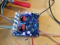
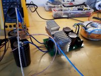
So today I finished both boards from Jim's audio, I hooked one up to 27 volt, and they work nicely, but, bias is a bit low, I measured 200 mili volt across ballast resistors that's roughly 0.6 amps, I would like it to run a bit hotter, 1-1.5 amps, I attach schematics, I hope any of you can help.
Btw offset is pretty good, only slight drift during warm up
Attachments
Take your time. This one took me months to learn as I found my own ways to do it at first. This whole amp is synergistic, as you change one thing it all settles as a result. There were many posts by a few good souls and I wish I'd collected links now. Some of it is in this thread but it spread over a few threads.
I'm still in doubt about power supply, it's running from cap multiplier, with 80000uf, but I also have four dual 18 volt toroidals 300w each, and around 50 22000uf 35v chemicon, to make a crc or clock plus, and also two 40amp 25 volt switch mode psu, I will give all three a test run and see which performs better
Attachments
ralf, is that a capacitance multiplier on the heatsink with the caps?
no, it`s a CRCRC PSU
Last edited:
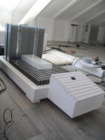
my Hiraga Monoblocks
some other design idea
multiple caps for psu, absolutely death silent
because of big heatsinks gets only handwarm
Is this a 30 watt version or an 8 watt version. & can you please share your schematic of your power supply.
since i use plus minus 24 Volts psu, i guess its about 20-25 watts
all the capacitors are paralled as used in many psu.
its a CRCRC arrangement. there are even some more caps than usual")
the white caps are 47uF/1200V MKP foil caps, which are nearest to the amp pcb.
its about (havent calculated exactly) 200.000uF - 0,1ohm - 200.000uF - 0,1ohm - 600.000uF...per monoblock little under 1F .
all the capacitors are paralled as used in many psu.
its a CRCRC arrangement. there are even some more caps than usual
the white caps are 47uF/1200V MKP foil caps, which are nearest to the amp pcb.
its about (havent calculated exactly) 200.000uF - 0,1ohm - 200.000uF - 0,1ohm - 600.000uF...per monoblock little under 1F .

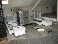
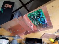
It was quite noticable in my case, well right now in testing I use passive crossover, but the goal is to run it all triamp, hiraga or the jlh for top, and a Bryson 4b clone for bottom, I'm in the progress of making two active crossovers also, not quite finished, awaiting RCA connectors, inner chassis is made of double sided PCs soldered together for good shielding , they contain mains filter, a toroid and a super regulator
Attachments
Last edited:
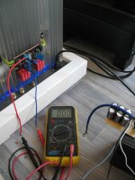
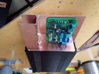
When adjusting bias yesterday, I noticed quite a difference between heatsink temperature and the actual transistor, I used ordinary insulators with paste, today at work I cut new to3 alu angles, so that each transistor has it's own 2.6 kilo heatsink and no insulators, that should decrease die temperature alot, each heatsink must the be isolated, but that's a easy task, and no high voltages involved, just pay attention to where you leave your tools, with that said and done I will try to increase bias to 2 amp like yours and see how it looks in arta.
When adjusting bias yesterday, I noticed quite a difference between heatsink temperature and the actual transistor, I used ordinary insulators with paste, today at work I cut new to3 alu angles, so that each transistor has it's own 2.6 kilo heatsink and no insulators, that should decrease die temperature alot, each heatsink must the be isolated, but that's a easy task, and no high voltages involved, just pay attention to where you leave your tools, with that said and done I will try to increase bias to 2 amp like yours and see how it looks in arta.
i have about 7kg heatsink per side with additional fans.
yes, the temperature directly on transitor is higher than on heatsink- i quess its about 50 degrees celsius.
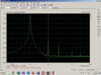
I got the transistors mounted directly to heatsink today, and let it cook with 1.5 amps for an hour, the to3 got close to 50 degrees Celsius, so well in Soa, boy it's to hot to test class A today close to 30 degrees outside, so ambient temperature is way higher than normal here, but managed to do a little Arta, here's 1w into 7 ohm load, noise is low, and second harmonics is dominant, I think it looks pretty decent, will do some more power testing this weekend 
Attachments
Yes ralf fans might be in idea, but yesterday I noticed that slight changes in airflow caused quite a offset drift, so cooling must be equal and even across heatsink and the driver board.
My driver boards have separate supply connectors, one for outputs and one for driver section, I have in spare some really low noise regulator boards, that can provide +/÷ 25 volts, I will try letting them run the driver section and see I they can reduce noise further, the arta is not accurate, there is a lot of 50/100 hz hum, probably due to the primitive setup on bench, proper chassis and grounding should yield better figures.
The quest goes on.
- Home
- Amplifiers
- Solid State
- Jean Hiraga Super Class A 30w Build