Great suggestions, lots more to learn, Oscilloscope, POWER!
Great suggestions, that was going to be my next task. I will do these modifications to one of the amplifier boards. Thoughts on changing capacitors to Russian audio teflon type, heard and read that these also can change the sound of the amplifier.
Board 1 will have these transisitors
MJL21194 + MJL21193 (your suggestion)
I will also do what you have done i.e changing R13/R14 etc
Board 2
I Will use different transistors here perhaps the MJL4302A/281A OR EXICON ECX10P20R ECX10N20R
From there i will modify the boards until i get the sound i like, i mean thats why we do this right?
Still so much to learn, i gather that i have to change the resistors based on the transistors i use as well as set the bias to the right level, i'm talking in basic terms here. Again something i will need guidance with as i only have basic knowledge.
You talk about "Matching" or "Pairing" how does one do this? I have a multimeter which i know measures impedance or ohms, is it as simple as that? I also have an oscilloscope (which i just purchased)
Velleman Handheld Scope with OLED Display HPS140MK2
Again basic usage, last time i used one of these was two decades ago. Either way i managed to measure the power output of various amplifiers using a function generator. Clearly it will be a big aid for building this amplifier (i hope!), it was fun and enjoyable and made me realise why i didn't do this earlier in my life.
POWER PSU
I'm going Dual mono to make a stereo amplifier. I want to have separate power supplies to them, so two transformers, two rectifying boards and smoothing caps etc
Or is it better to just have one large transformer?
Thoughts on rail voltage? This seems to fluctuate amongst builders, traditionally it was 24v? Some use 30v? I think you prefer 22v?
I want to go two EI transformers, thoughts were
21-0-21 or 24-0-24 400va each
NEW Mains Isolation Transformer 300VA 230V PRI. 48V (24-0-24V) SEC., CCM300/48 | eBay
or i could get some custom made ones? might be cheaper? or work out better?
Transformer design - Custom transformer design and custom transformer manufacturer
Also read the rectifiers have to handle 50amps?
Think after learning all this i want to help others and make this information more readily available.
I'll keep you posted! Thank you again.
From the start i can sugest that you replace and try to adapt to the pcb the 0R33, R13/R14 (from pcb photos) Koa Speer wirewound resistors with 3*1ohm/3w(minimum) metal oxide or metal film (the metal film ones are better because they have less noise , but are very expensive at 1% tolerance for buying lots for matching) instead of one. I use metal oxide here with succes. With this tweak the sound gets even better. I sugest you compare them both, but i bet that you will stick to the metal oxides instead of the wirewound...
The R15/R16 (from pcb photos)@1K8 will get hot so i sugest for lower noise and prolongued expectancy life and stability use 2*3k6/2w or 3w metal oxide or metal film (i use metal oxide). I definetly dont recomend carbon composite here. I didnt perceived any sound improvement with this tweak but i remember a friend of mine that sayed "in class a, the bigger, the better"and now, after almost two years of happy listening i'm glad that i listened to his advice. I'm on the safe side with my amp. I still have some exotic upgrades for the input at the passive componnents chapter in the future (allready buyed them) but didnt had time yet.
Cheers
Sergiu
When I have some time, I intend to try my Krell Ksa50 clone using high quality USA SMPSs. I have enough to use 1 per rail per channel. 800 watts total.
I have a mechanically buzzy transformer in there now, and before I spring for a new one - I think it's worth an investigation. I might find myself pleasantly surprised
I have a mechanically buzzy transformer in there now, and before I spring for a new one - I think it's worth an investigation. I might find myself pleasantly surprised
Please don't use a SMPS with this amp. I like SMPS, but it's just not right for this amp. I built a couple of the 20W version from the original kits back in the 80s and also know the production model well, even spent some time visiting the production line.
On my first build, I cheaped out and went with a toroid transformer. OK, but not the best. My next build was an EI transformer and I liked it better. Never could find an R core of the right specs, but always wanted to try it.
The Massive Passive PSU is a large part of this amp's charm.
On my first build, I cheaped out and went with a toroid transformer. OK, but not the best. My next build was an EI transformer and I liked it better. Never could find an R core of the right specs, but always wanted to try it.
The Massive Passive PSU is a large part of this amp's charm.
On my first build, I cheaped out and went with a toroid transformer. OK, but not the best. My next build was an EI transformer and I liked it better. Never could find an R core of the right specs, but always wanted to try it.
C-cores Pano....c-cores....best compromise....
I Will use different transistors here perhaps the MJL4302A/281A OR EXICON ECX10P20R ECX10N20R
Can you use mosfets with this amp?
Great suggestions, that was going to be my next task. I will do these modifications to one of the amplifier boards. Thoughts on changing capacitors to Russian audio teflon type, heard and read that these also can change the sound of the amplifier.
My friend, why change to russian and spend more money where it isnt the case, these caps are not in the signall path anyway... The board that you buyed has allready what's needed. I'm not trying to convice you to construct it cheap, instead i'm telling you to put more money into the key points of this amp.
For example in the C11/C13 position from pcb photo you can paralell two caps of very good quality to achieve 1500~2200uF, this mod will add even more clarity ,microdetails and depth.
Board 1 will have these transisitors
MJL21194 + MJL21193 (your suggestion)
I will also do what you have done i.e changing R13/R14 etc
Board 2
I Will use different transistors here perhaps the MJL4302A/281A OR EXICON ECX10P20R ECX10N20R
I still have those MJL4302A/281A , but thought they where too fast for me. They sounded good, specially for trance; dont get me wrong, but a bit too fast for me on the other stuff. It was abit hard to catch some details in some heavy simfonic orchestra and in some lounge melodyes where like Buda Bar was trying to catch a train, and didnt have time to sing...
From there i will modify the boards until i get the sound i like, i mean thats why we do this right?
Right!
Still so much to learn, i gather that i have to change the resistors based on the transistors i use as well as set the bias to the right level, i'm talking in basic terms here. Again something i will need guidance with as i only have basic knowledge.
Follow the instructions from Jims's kit. If he didnt provide the bias adj setting, it should be pretty straight.
You talk about "Matching" or "Pairing" how does one do this? I have a multimeter which i know measures impedance or ohms, is it as simple as that? I also have an oscilloscope (which i just purchased)
You dont need matching yet, because the kit is matched as Jim says. You will need matching only if you use other trannies than supplyied in the kit. It's allot to say here.. Please look at a tutorial on the web here or look on the diy web site. I used a usual chinese dmm with 1mA matching curent (you will find this aspect on the dmm specs for hfe) for inputs and driver.
Velleman Handheld Scope with OLED Display HPS140MK2
Again basic usage, last time i used one of these was two decades ago. Either way i managed to measure the power output of various amplifiers using a function generator. Clearly it will be a big aid for building this amplifier (i hope!), it was fun and enjoyable and made me realise why i didn't do this earlier in my life.
You will only need the scope to measure the amps output and ripple if wanted.
POWER PSU
I'm going Dual mono to make a stereo amplifier. I want to have separate power supplies to them, so two transformers, two rectifying boards and smoothing caps etc
Two big transformers (400VA each) +two small encapsulated ones just for the inputs (look for 1A secondary versions). Also if you want to go premium, use 4 bridges with soft recovery dyode types, matched diodes instead of encapsulated soft recovery bridges.
Or is it better to just have one large transformer?
Better two, because of less mechanical noise, better heat dissipation etc.
Thoughts on rail voltage? This seems to fluctuate amongst builders, traditionally it was 24v? Some use 30v? I think you prefer 22v?
I prefer 1.65A bias because the sound gets even more opened and relaxed. So i prefer bigger bias, because i tried it with 24Vcc and 27~28Vcc and the result was the same.
Beware that, when you breach the 24Vcc and specially the 1.5A bias barrier, the the temps goes through the roof..
I want to go two EI transformers, thoughts were
21-0-21 or 24-0-24 400va each
NEW Mains Isolation Transformer 300VA 230V PRI. 48V (24-0-24V) SEC., CCM300/48 | eBay
Better go with the 21-0-21 400va each, you will have almost 28Vcc after caps in full load, and 38w sinus output.
Dont get confused by the lower output power. This amp sounds very loud for its output. Just buy more sensitive speakers, new or sh and you will be blown away for shure.
or i could get some custom made ones? might be cheaper? or work out better?
Transformer design - Custom transformer design and custom transformer manufacturer
Usually custom ones are more expensive, but better quality if you know what to ask. If you go custom ask for a bicafillar winding as i did, because you will get same impedance on both secondaries (like in the case of C cores or R cores).
Also read the rectifiers have to handle 50amps?
I used 60A ultra fast soft recovery diodes, matched with my dmm. This way i could use smaller rads and prolongue the expectancy life of these little babyes.
The diodes i used are these 60APU04PBF VISHAY - Diod?: redresoare | TME - Componente electronice (VISHAY 60APU04PBF). They get warm when power up and then run cold.. The amp doesnt draw much current, instead the cap bank drains allot at powering up.
Think after learning all this i want to help others and make this information more readily available.
I tryied to open a builders thread with all that i know, and pick all the info from all my past posts and experiences, but bellieve me, its allot to collect and put together + that my family got bigger from this March wich putted even my rubanoide speakers (from "A DIY Ribbon Speaker of a different Kind ") on the second place and are not fully assembled...
I'll keep you posted! Thank you again.

You're welcomme. I will try to help you as much as i can.
Cheers
Hi VishalK
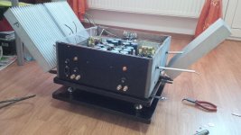
The second photo of Amplifier is mine. I would like to suggest you some points.
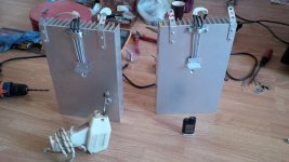
1. This amp really gets very very hot and it will need a massive heat sink, so do not compromise on heat sink. The Heat sink size of my amplifier is 205 mm Width x 117 mm Height x 82 mm fin length. This is size for each heat sink. I have used 4 of them (each for a transistor) and they also really get very hot.
2. I tested at least 4 different pairs of transistors and the most suited for my taste were
For Output Transistor : NJW0281G & NJW0302G
For Driver Transistor : 2SC4793 & 2SA1837
There was a great improvement in clarity of Vocals & Highs by using the above transistors. The vocals did not get mixed up with high frequencies. I would advise you to take a trial of these transistors also.
3. Try to avoid any ground loop during wiring or else there will be hum. Take care of the wiring during the assembly itself.
Enjoy your built journey.
Regards
Sadik Bhatkar
The second photo of Amplifier is mine. I would like to suggest you some points.
1. This amp really gets very very hot and it will need a massive heat sink, so do not compromise on heat sink. The Heat sink size of my amplifier is 205 mm Width x 117 mm Height x 82 mm fin length. This is size for each heat sink. I have used 4 of them (each for a transistor) and they also really get very hot.
2. I tested at least 4 different pairs of transistors and the most suited for my taste were
For Output Transistor : NJW0281G & NJW0302G
For Driver Transistor : 2SC4793 & 2SA1837
There was a great improvement in clarity of Vocals & Highs by using the above transistors. The vocals did not get mixed up with high frequencies. I would advise you to take a trial of these transistors also.
3. Try to avoid any ground loop during wiring or else there will be hum. Take care of the wiring during the assembly itself.
Enjoy your built journey.
Regards
Sadik Bhatkar
Hi Sadik,
Those drivers where best for me two. Very good sounding pairs indeed.
Sadik have you compared the njw 30Mhz outputs with the mj/mjl21193/94 that i sugested?
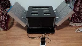
Vishalk, Sadik is right.. just take a look at my final rads used in the pics bellow.
Beware of the huge heat disipation Vishalk!
Those drivers where best for me two. Very good sounding pairs indeed.
Sadik have you compared the njw 30Mhz outputs with the mj/mjl21193/94 that i sugested?
Vishalk, Sadik is right.. just take a look at my final rads used in the pics bellow.
Beware of the huge heat disipation Vishalk!
Attachments
Hi VishalK
The second photo of Amplifier is mine. I would like to suggest you some points.
A very nice Build Sadik, neat and tidy.
1. This amp really gets very very hot and it will need a massive heat sink, so do not compromise on heat sink. The Heat sink size of my amplifier is 205 mm Width x 117 mm Height x 82 mm fin length. This is size for each heat sink. I have used 4 of them (each for a transistor) and they also really get very hot.
Don't Worry i will be using some heavy duty heatsinks, i've been told many times it is important.
2. I tested at least 4 different pairs of transistors and the most suited for my taste were
For Output Transistor : NJW0281G & NJW0302G
For Driver Transistor : 2SC4793 & 2SA1837
There was a great improvement in clarity of Vocals & Highs by using the above transistors. The vocals did not get mixed up with high frequencies. I would advise you to take a trial of these transistors also.
Currently the kit comes supplied with MJE15035J/MJE150034G i will buy the driver transistors you suggest. Can i leave those in and just change the output transistors instead? Do i have to modify anything else on the board because i am changing the driver and output trannies?
3. Try to avoid any ground loop during wiring or else there will be hum. Take care of the wiring during the assembly itself.
Group Loop? not sure what this is?
I would be interested in your design for your power supply, do you have any more information or a thread i can read and view your work?
Enjoy your built journey.
Enjoying as we speak
Regards
Sadik Bhatkar
Oh my word!!!! Looks like its going to fly! I'm making sure the heatsinks are more than suitable, i think ill provide each transistor with 2.5-3kg of extruded finned aluminium to be on the safe side.
Hi Sadik,
Those drivers where best for me two. Very good sounding pairs indeed.
Sadik have you compared the njw 30Mhz outputs with the mj/mjl21193/94 that i sugested?
Vishalk, Sadik is right.. just take a look at my final rads used in the pics bellow.
Beware of the huge heat disipation Vishalk!
Last edited:
Yup, they have almost 3kg each just for 38w, and do get pretty warm in the summer, that's why they are oriented at preciselly 45 degree angle (for the summer when the chimney effect diminishez) ... imagine Dan's 58w version how warm can go .
You dont have to modify the pcb, just be carefull at the pinouts of the newly installed trannies.
Sadik is using a capacitance multiplier. You can find his schm and description on the big hiraga thread (at the end) wich has more than 100 pages.
If i remember well Sadik was using the CM from ESP site.
Can you post again the details here Sadik?
Thanks
imagine Dan's 58w version how warm can go .You dont have to modify the pcb, just be carefull at the pinouts of the newly installed trannies.
Sadik is using a capacitance multiplier. You can find his schm and description on the big hiraga thread (at the end) wich has more than 100 pages.
If i remember well Sadik was using the CM from ESP site.
Can you post again the details here Sadik?
Thanks
Please don't use a SMPS with this amp. I like SMPS, but it's just not right for this amp. I built a couple of the 20W version from the original kits back in the 80s and also know the production model well, even spent some time visiting the production line.
On my first build, I cheaped out and went with a toroid transformer. OK, but not the best. My next build was an EI transformer and I liked it better. Never could find an R core of the right specs, but always wanted to try it.
The Massive Passive PSU is a large part of this amp's charm.
Hello Pano,
It seems you and me have both been in Paris at the time ( early eighties) when there were lots of Hiraga amps around. Back then the French diy community did do lots of test, trying to improve it.
Actually now there are still people using this amp in France. At Melaudia forum you can read what they did try about improving the power supply. SMPS too but most of them agree that with amp you need a classic power supply with big caps.
At that time i did ask the staff in the shop in Paris that sold this amp if it would be a good idea to use CLC power supply instead of CRC because they just did make a choke for their Nemesis amp. They said SURE so i did.
Right now Lundahl is making some high current chokes that would be even better.
I did mention them before here on several threads.
R-core, double C-core or even EI core usually sound nicer than the ones everybody is using. But Pano we dont have to listen to these amps so why worry?
Greetings, Eduard
Hi Sergiu,
During my built i did learned a lot from your thread on this Amp. Below is the link of my drive folder.
https://drive.google.com/open?id=0B2a9DN9GbmtBWm5xY2tqT3BYZDQ
You will find complete photos of my built in this folder, including layout of Cap Multiplier.
There is a zip file in the folder. It has recorded music samples with same setup for different transistors. This recording was done on cell phone which is not the correct way but experienced ears will have a good idea on how they sounded in real. The recording in Sample 1 sounded almost same for output transistors like 2SC5200 & 2SA1943, MJL21193/94, there was one more which i forgot the number they were metal can type transistors. Sample 2 is recorded with Output Transistor NJW0281G & NJW0302G & Driver Transistor 2SC4793 & 2SA1837. You can download the zip file and listen to them and compare yourself. I found Sample 2 had more presence of vocal and great separation of frequencies, which makes the sound even more natural.
This 30 Watt is really is Beast, Do not underestimate the 30 Watts Power in class A, I have driven PA speakers with this Amplifier, 2 Mids of 12" on a single channel, There are 3 Video files of this testing which can be download
Regards,
Sadik Bhatkar
Hi Sergiu,
During my built i did learned a lot from your thread on this Amp. Below is the link of my drive folder.
https://drive.google.com/open?id=0B2a9DN9GbmtBWm5xY2tqT3BYZDQ
You will find complete photos of my built in this folder, including layout of Cap Multiplier.
There is a zip file in the folder. It has recorded music samples with same setup for different transistors. This recording was done on cell phone which is not the correct way but experienced ears will have a good idea on how they sounded in real. The recording in Sample 1 sounded almost same for output transistors like 2SC5200 & 2SA1943, MJL21193/94, there was one more which i forgot the number they were metal can type transistors. Sample 2 is recorded with Output Transistor NJW0281G & NJW0302G & Driver Transistor 2SC4793 & 2SA1837. You can download the zip file and listen to them and compare yourself. I found Sample 2 had more presence of vocal and great separation of frequencies, which makes the sound even more natural.
This 30 Watt is really is Beast, Do not underestimate the 30 Watts Power in class A, I have driven PA speakers with this Amplifier, 2 Mids of 12" on a single channel, There are 3 Video files of this testing which can be download
Regards,
Sadik Bhatkar
Thank you Sadik,
I just downloaded all your pcb's. I love them, and all your work ofcourse. I'm glad that you finished your amp with succes.
I will analise your sound samples tonight when i come home from work. Interesting toughts about the outputs, but i think that the passive components AND PSU play a very important role too here. Cant wait to come home tonight.
Indeed 30 w class A is very much, especially on 12 (yours) or 15 inch PA (i bought a pair and have to make some enclosures for them) ...
Cheers
Sergiu
Yes, I can certainly see a CLC being a good idea, but expensive and heavy. Nice to know you built one and like it.At that time i did ask the staff in the shop in Paris that sold this amp if it would be a good idea to use CLC power supply instead of CRC because they just did make a choke for their Nemesis amp. They said SURE so i did.

Can you use mosfets with this amp?
Can you?
Can you?
I read somewhere that you can?!
Yes, I can certainly see a CLC being a good idea, but expensive and heavy. Nice to know you built one and like it.
Hello Pano,
If you use the lundahl LL2733 and put the 2 coils in parallel you will get a 100mH choke with 3,4 current rating ( will saturate at 5,4 A ) and a 0,85 ohm dcr. In the USA they are 100$ a piece and you need two.
I have been using lundahl chokes in many designs. Even with big currents and choke input they will not protest ( buzz)
You could try serial connection but i never use that one for a solid state power amp. Maybe dcr will be to high.
A vietnamese friend will use the LL2733 for choke input in a Nelson Pass design.
Later on the hiraga people did also start using chokes.
The ll2733 is 1,35 kilogramme so not that heavy, not that big. And if you think 200$ is to expensive you better not build a Hiraga amp. Remember these chokes have infinite lifetime.
And most of the words dedicated to the Hiraga amp in the past were about the power supply.
greetings, Eduard
- Home
- Amplifiers
- Solid State
- Jean Hiraga Super Class A 30w Build