Crestron 16x60 Mod Project: 12V triggerd, Bridgeable to 5x200W/6x60W
I have just completed modifying my Crestron 16x60 to have 5 8 ohm bridgeable channels.
The amplifier is bridgeable using a simple toggle switch without the need for their external bridge modules. I did this by changing the amplifier boards to match the exact circuit that they use on their bridgeable 2x60 amplifier!
I have been looking at Crestron amplifiers for a while now given that they have so many channels and are made by ATI. In the past I had modified a 2x60 amplifier to work without cresnet just using an external 24V power supply.
This modification to the 16x60 goes much further in a lot of ways. It changes the system to fully run on a 12v trigger. 12V Trigger Modification details:
The main relay was replaced with an equivalent 12V version.
The crestron control board was removed and replaced with a 12V trigger via a 3.5mm mono connector (one or the other can be used, they aren't intended to be used at the same time). This is connected to the main relay via a small custom PCB. The amp still requires a 12v trigger input in order to turn on because it has no standby transformer of its own. Alternatively I also added a DC input jack so that a 12V wall wart could be used instead of the 12v trigger.
.jpg")
Due to the cost of replacing all of the output board relays with 12V relays they were removed and replaced with 20ga copper wires. The relay control and output monitoring board was also removed which simplifies things and gives more space. Many amplifiers such as my Adcoms don't use output board relays, this can result in a small power on pop but is not a problem.
I suppose I could have left the 24v relays there and could have made them work via a 12v trigger if I was willing to use both a 24V wall wart and add a relay to switch the 24v input with the 12v trigger. For my use model I just removed the output board relays instead but in retrospect it required a lot of desoldering and it might have been easier to add the extra relay and just deal with the wall wart.
.jpg")
The Bridging Idea
While the amps will probably drive 80watts or more to each channel before distortion I was curious to see if they couble be bridged...
Bridging it pairs channels (which are already on a shared board) and makes the amp much more useful in a home theater environment giving it a great deal of power on 5 channels with 6 channels left at 60w to drive surround or atmos speakers. This amplifier can now be used to handle 7.4.1 atmos all in one package.
My custom Crestron 16x60 can now be configured the following ways:
16x60, 2x200@8ohm/12x60, 3x200@8ohm/10x60, 4x200@8ohm/8x60, 5x200@8ohm/6x60
The Crestron 2x60 amplifier is exactly the same schematically as the 12x60 and 16x60 crestron amplifiers except it has one channel per amplifier board instead of two and it is bridgeable. The bridge feature turns out to just be a switch on the input board along with a feedback resistor.
Bridged Specs for the 2x60 are:
Output Power 20Hz to 20kHz, both channels driven at rated THD:
200 watts at 8 ohms bridged
Power Bandwidth 3Hz to 50kHz, +0/-3dB
Total Harmonic Distortion (THD) ≤0.03% at full power
The 16x60 is actually listed as 220W when bridged with external CNXBRMO modules but they specify to only bridge 4 channels. I bridged 5 channels and don't see this as an issue for home theater where it is very very rare to power more than 3 channels at full power. Rather than claiming 220W it seems more reasonbale to expect 200W given that it is using the bridge circuit from the 2x60 amplifier. I made every attempt to keep my addon board very compact to emulate the 2x60 design.
Bridge Module Addition/Modification Method
I found an article on Elliot Sound Products describing project 20:
Simplest Ever Bridging Adapter for Amplifiers
I was curious and discovered that this is EXACTLY what crestron did on the 2x60 amplifier except the crestron has input filter capacitors on both the non inverting and inverting inputs.
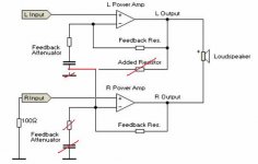
I duplicated the circuit from the 2x60 on this board:
The top pin of the connector is the output to the bridge switch from the 28k feedback resistor that comes from the positive phase amplifier output.
The bottom pin of the connector is the input from the bridge switch which connects to the top pin.
The two capacitors connect in parallel from the 1k resistor to ground and the input (bottom pin).
The white jumper wire on the left connects the square capacitor output to the inverted input of the bridged amp.
The white jumper wire on the right connects to the input side of the electrolytic capacitor.
The outputs of the capacitors connect to the bottom left pin which goes directly to the inverted input of the negative phase amplifier.
.jpg")
.jpg")
I desoldered and reused the input capacitors (C8A/C9A) from the 16x60 inverting input (the 1k input resistor R14A can also be resused). I then added a high quality 1% 28k resistor to the circuit as the only new component other than the board/wires/switch. The 2x60 amplifier has this resistor on each amplifier board (even though only one uses it) so that the boards are interchangable.
Note that instead of buying 28k resistors there are many of them on the output sampling board that is not needed for a standalone amplifier. This was one of the boards that I removed so they could have been stolen from that board.
Note that I chose to modify channel A on this board which is the Left channel to stay with the convention of having the Right channel be the positive side of the bridged amplifier. This picture shows the green board version of a 16x60 board which was my prototype where the yellow board version has a slightly different layout and component naming. The differences are very small for the most part. The yellow board also uses different output devices on the amplifiers which surprised me.
The red wire is from the ouptut of the Right channel to the feedback resistor on the bridge circuit. The board already has a via there to go to the other side of the board so I simply sucked out the solder and added the wire through the via (soldering it on both sides of the board).
The 1k resistor is connected to ground and if the bridge circuit is not enabled it connects GND->1k->Input Filter->Inverting Input.
.jpg")
The board connects to Ground via the top connection where C9A was removed from the board. The right side of R14A goes to the inverting input of the amplifier. The board connects to the other side of those components just to hold it in place. There is no connecto to the board accross C8 but I filled in the vias with solder just to make the best possible electrical connection back to ground.
The changes to the board can easily be undone if desired.
.jpg")
The addon board is then soldered to the back side of the amplifier board using 4 header pins (which happen to align close enough to work well).
.jpg")
I then drilled holes on the back panel of the 16x60 to add a DPDT switch. The 2x60 uses a 3 position switch such that it supports Stereo, Bridged, and Summing (the right input also feeds the left amplifier in dual mono mode). The switch is directly on the input board of the 2x60. I got a deal on some 2 position switches so I skipped the Summing (dual mono) configuration.
I must say that it is CRITICAL to use the best switch you can find. I initially experimented with some ebay switches and found that they added cross channel distortion when used. I had to buy top of the line ALCO switches to eliminate the noise. Once I did that there is no extra cross channel distortion from the switch.
.jpg")
To connect the switch I de-soldered the ground pin from the left RCA input and put the ground connection in the same circuit board hold with it and re-soldered it and connected the other end to the switch. For input grounding I simply soldered directly to the back side of the RCA connector (which is a very easy and robust solder point).
I then used a twisted pair wire back from the switch to the bridging addon board.
The good thing about the 2x60's bridge circuit design is that if the switch is open then it is as if the bridge module isn't there, it only connects the feedback resistor when the switch is in bridge mode. I actually have 6 modified boards in my amplifer but one of them isn't connected and it works as normal.
New back Panel:
I originally drilled holes to add bridging modules to all 8 boards but then realized that I only need 5 channels to be bridged. I plugged the holes with stainless hardware. It is possible to rearrange the boards but I found it best to distribute the bridged channels accross the two torroid transformers.
I need to redo the labels with my label maker and get them on squarely at some point.
.jpg")
Removed components:
Bag of 24v output relays
Original 24v main relay
Crestron Control board
Output board (and wires) for crestron controller power monitoring.
Output wires from the distortion detect to the crestron board.
.jpg")
-Rich
I have just completed modifying my Crestron 16x60 to have 5 8 ohm bridgeable channels.
The amplifier is bridgeable using a simple toggle switch without the need for their external bridge modules. I did this by changing the amplifier boards to match the exact circuit that they use on their bridgeable 2x60 amplifier!
I have been looking at Crestron amplifiers for a while now given that they have so many channels and are made by ATI. In the past I had modified a 2x60 amplifier to work without cresnet just using an external 24V power supply.
This modification to the 16x60 goes much further in a lot of ways. It changes the system to fully run on a 12v trigger. 12V Trigger Modification details:
The main relay was replaced with an equivalent 12V version.
The crestron control board was removed and replaced with a 12V trigger via a 3.5mm mono connector (one or the other can be used, they aren't intended to be used at the same time). This is connected to the main relay via a small custom PCB. The amp still requires a 12v trigger input in order to turn on because it has no standby transformer of its own. Alternatively I also added a DC input jack so that a 12V wall wart could be used instead of the 12v trigger.
Due to the cost of replacing all of the output board relays with 12V relays they were removed and replaced with 20ga copper wires. The relay control and output monitoring board was also removed which simplifies things and gives more space. Many amplifiers such as my Adcoms don't use output board relays, this can result in a small power on pop but is not a problem.
I suppose I could have left the 24v relays there and could have made them work via a 12v trigger if I was willing to use both a 24V wall wart and add a relay to switch the 24v input with the 12v trigger. For my use model I just removed the output board relays instead but in retrospect it required a lot of desoldering and it might have been easier to add the extra relay and just deal with the wall wart.
The Bridging Idea
While the amps will probably drive 80watts or more to each channel before distortion I was curious to see if they couble be bridged...
Bridging it pairs channels (which are already on a shared board) and makes the amp much more useful in a home theater environment giving it a great deal of power on 5 channels with 6 channels left at 60w to drive surround or atmos speakers. This amplifier can now be used to handle 7.4.1 atmos all in one package.
My custom Crestron 16x60 can now be configured the following ways:
16x60, 2x200@8ohm/12x60, 3x200@8ohm/10x60, 4x200@8ohm/8x60, 5x200@8ohm/6x60
The Crestron 2x60 amplifier is exactly the same schematically as the 12x60 and 16x60 crestron amplifiers except it has one channel per amplifier board instead of two and it is bridgeable. The bridge feature turns out to just be a switch on the input board along with a feedback resistor.
Bridged Specs for the 2x60 are:
Output Power 20Hz to 20kHz, both channels driven at rated THD:
200 watts at 8 ohms bridged
Power Bandwidth 3Hz to 50kHz, +0/-3dB
Total Harmonic Distortion (THD) ≤0.03% at full power
The 16x60 is actually listed as 220W when bridged with external CNXBRMO modules but they specify to only bridge 4 channels. I bridged 5 channels and don't see this as an issue for home theater where it is very very rare to power more than 3 channels at full power. Rather than claiming 220W it seems more reasonbale to expect 200W given that it is using the bridge circuit from the 2x60 amplifier. I made every attempt to keep my addon board very compact to emulate the 2x60 design.
Bridge Module Addition/Modification Method
I found an article on Elliot Sound Products describing project 20:
Simplest Ever Bridging Adapter for Amplifiers
An externally hosted image should be here but it was not working when we last tested it.
I was curious and discovered that this is EXACTLY what crestron did on the 2x60 amplifier except the crestron has input filter capacitors on both the non inverting and inverting inputs.
I duplicated the circuit from the 2x60 on this board:
The top pin of the connector is the output to the bridge switch from the 28k feedback resistor that comes from the positive phase amplifier output.
The bottom pin of the connector is the input from the bridge switch which connects to the top pin.
The two capacitors connect in parallel from the 1k resistor to ground and the input (bottom pin).
The white jumper wire on the left connects the square capacitor output to the inverted input of the bridged amp.
The white jumper wire on the right connects to the input side of the electrolytic capacitor.
The outputs of the capacitors connect to the bottom left pin which goes directly to the inverted input of the negative phase amplifier.
I desoldered and reused the input capacitors (C8A/C9A) from the 16x60 inverting input (the 1k input resistor R14A can also be resused). I then added a high quality 1% 28k resistor to the circuit as the only new component other than the board/wires/switch. The 2x60 amplifier has this resistor on each amplifier board (even though only one uses it) so that the boards are interchangable.
Note that instead of buying 28k resistors there are many of them on the output sampling board that is not needed for a standalone amplifier. This was one of the boards that I removed so they could have been stolen from that board.
Note that I chose to modify channel A on this board which is the Left channel to stay with the convention of having the Right channel be the positive side of the bridged amplifier. This picture shows the green board version of a 16x60 board which was my prototype where the yellow board version has a slightly different layout and component naming. The differences are very small for the most part. The yellow board also uses different output devices on the amplifiers which surprised me.
The red wire is from the ouptut of the Right channel to the feedback resistor on the bridge circuit. The board already has a via there to go to the other side of the board so I simply sucked out the solder and added the wire through the via (soldering it on both sides of the board).
The 1k resistor is connected to ground and if the bridge circuit is not enabled it connects GND->1k->Input Filter->Inverting Input.
The board connects to Ground via the top connection where C9A was removed from the board. The right side of R14A goes to the inverting input of the amplifier. The board connects to the other side of those components just to hold it in place. There is no connecto to the board accross C8 but I filled in the vias with solder just to make the best possible electrical connection back to ground.
The changes to the board can easily be undone if desired.
The addon board is then soldered to the back side of the amplifier board using 4 header pins (which happen to align close enough to work well).
I then drilled holes on the back panel of the 16x60 to add a DPDT switch. The 2x60 uses a 3 position switch such that it supports Stereo, Bridged, and Summing (the right input also feeds the left amplifier in dual mono mode). The switch is directly on the input board of the 2x60. I got a deal on some 2 position switches so I skipped the Summing (dual mono) configuration.
I must say that it is CRITICAL to use the best switch you can find. I initially experimented with some ebay switches and found that they added cross channel distortion when used. I had to buy top of the line ALCO switches to eliminate the noise. Once I did that there is no extra cross channel distortion from the switch.
To connect the switch I de-soldered the ground pin from the left RCA input and put the ground connection in the same circuit board hold with it and re-soldered it and connected the other end to the switch. For input grounding I simply soldered directly to the back side of the RCA connector (which is a very easy and robust solder point).
I then used a twisted pair wire back from the switch to the bridging addon board.
The good thing about the 2x60's bridge circuit design is that if the switch is open then it is as if the bridge module isn't there, it only connects the feedback resistor when the switch is in bridge mode. I actually have 6 modified boards in my amplifer but one of them isn't connected and it works as normal.
New back Panel:
I originally drilled holes to add bridging modules to all 8 boards but then realized that I only need 5 channels to be bridged. I plugged the holes with stainless hardware. It is possible to rearrange the boards but I found it best to distribute the bridged channels accross the two torroid transformers.
I need to redo the labels with my label maker and get them on squarely at some point.
Removed components:
Bag of 24v output relays
Original 24v main relay
Crestron Control board
Output board (and wires) for crestron controller power monitoring.
Output wires from the distortion detect to the crestron board.
-Rich
Simplest Ever Bridging Adapter ?
It can be done without an extra resistor, even a resistor and capacitor less
Mona
Perhaps simple rather than simplest would have been a better choice of words. They werent my words.
")
It was interesting to see that Crestron (ATI) followed that schematic on thr 2x60. I just replicated it because I knee it would work.
I will think about your schematic more. One might be easier to do than the other or better lend it's self to being switchable between stereo and bridged mono.
Thanks,
Rich
hi Rich I stumbled on your great conversion while looking for the cnxbrmo bridging interface. to start I have very limited amp modification experience. I have a 16x60 in great shape. I would like to have it modded like yours. Anyway I could send it to you for the update? Alternately Could I pay you to walk me through? I do have very diy skills and all tools required to do the job. Any heilp you can send my way would be great. I live in SF area of California. thanks Steve 925 768 0895
I stumbled on this thread by accident, but it is very timely! I just scored a non-working Crestron 16x60 amp. I did the "override" while feeding 24V into the pins at the back. I got a relay to click on but nothing more. My guess is that the soft-start board (e.g. NTC thermistor) has died, or at least I hope that is it. I have not yet opened it up since I have a bunch of other projects stacked up and I am falling behind schedule...
My plan is to perform surgery on the amp to split it into two 8 channels amps, and each of these will certainly be much easier to lift! I believe each of the two transformers drives four of the eight output boards, so a two-way split seems possible. I did not know that each board has speaker relays, so that is nice to know. Of course if I could get the schematic I would be much happier, but for the price I paid for it (peanuts! and I picked it up in person from the seller so "shipping" was free) I have an interesting project on my hands. In the worst case that the amp is trashed, at least I now own two more nice toroidal transformers....
PS: why not just build an outboard bridging module that produces buffered and inverted buffered signal from a mono input. Use that to bridge whatever channel pairs you desire without having to do too surgery on the amp boards...
Last edited:
HiThe only reason I found this site was my search for such a device instead of digging into the amp. Crestron made such a device called the CNXBRMO Bridging interface. Super cheap and compact but I cant find one.
I'm not into making electical components so I would not know if I'm using coponents suitable for this amp. Are thay generic one size fits all amps?
Such a shame not to put such a nice amp to good use.
Any suggestions? Since the amps are going for such a small price I dont want to spend too much.
Thank you
Steve
925 768 0895
I would not keep posting your phone number...
But to address your problem, you do not need to do anything to the amp at all. I will first assume that you have figured out how to use this amp as a power amp. So, how to bridge? Well, you can create two out of phase signals externally, and feed them to pairs of inputs on the amp. Then you connect the speaker across the "hot" (red) terminals of these two amp channels to get your bridged channel. There is no need to open the cover or make any modifications whatsoever to the amp itself.
The piece of equipment that will do this for you is called an "unbalanced to balanced line converter". Not all of these will work for this purpose - they must actively drive (put signal on) each line of the balanced output. I own such a unit that is good quality (e.g. built well and good sound quality) and that is made by Henry Engineering and is called the "Matchbox HD" or sometimes just the "Matchbox". I know it will work because I have the circuit schematic. It's in the manual - you can read it yourself.
Here is a link to a Matchbox HD currently for sale (used) on Ebay:
Henry Engineering The Matchbox IHF Pro Stereo Interface Amplifier | eBay
The Matchbox will allow you to create two bridged channels from two unlabanced (RCA) inputs. For each channel you want to bridge, connect the input RCA cable to one of the inputs. The two output channels are then taken from the XLR output for that channel. You also need a cable that has on one end the mating XLR connector and on the other end breaks out the "hot" and "cold" pins to separate RCA cables. Here is an example of such a cable:
SA-Y5 (4 Pack) | Splitter Cables | Y Cables | Patch Cables | 1 XLR Female to 2 RCA Male | 6 Inches – seismicaudio
The cables are only 6 inches long. You might phone the company to make sure that the two RCA ends connect one to the hot pin and one to the cold pin of the XLR. I think so, but you should verify this. Other companies may offer similar products but this is a good deal on a 4-pack.
If you buy two of the Matchbox and get the four-pack of cables you can then bridge EIGHT of the channels of the Crestron amp into FOUR bridged channels. Note that the bridged channels should be connected to 8 Ohm (or higher) loads only.
Any questions? Please post them in this thread and I will try to answer them.
Last edited:
I'm looking to do the exact same thing as posted in this thread - bridge 10 of the channels to create a 5x200W output for the mains and use the other 6 for 2 rear surround and 4 Atmos speakers. Curious if this Henry Matchbox model will work for what you described, or will only the newer Matchbox HD work? Henry Engineering The Matchbox II 2 IHF Interface Amplifier | eBay
They seem to do the same thing, not sure if there's any difference other than the physical design of the box? The one you posted does have level adjustments while this one does not, but I don't see how those would offer any benefit with this type of use.
Alternatively, why couldn't you just use a passive RCA y-cable and modify one of the output ends so that the polarity is reversed? Wouldn't that achieve the same thing?
"Balanced" outputs have no requirement that both pins are actively driven. Many modern implementations just drive the hot pin. You can check by sending a sine wave (60Hz would be a good choice!) at full level via the XLR and testing the voltage between hot and gnd and then cold and gnd.
By the way, I totally disassembled my amp. It conveniently can be broken down into the eight output modules (which each have onboard rectifier and caps) and the two transformers. Each transformer connects to four of the output modules, so you can split the amp into two 8-channels amps quite easily. Just need to add a soft-start to each tranny and possibly the output LCR networks. Nice! I can bridge a couple of the channels on each side (into 8 Ohms only) and still have lots of channels leftover for a multiway system.
By the way, I totally disassembled my amp. It conveniently can be broken down into the eight output modules (which each have onboard rectifier and caps) and the two transformers. Each transformer connects to four of the output modules, so you can split the amp into two 8-channels amps quite easily. Just need to add a soft-start to each tranny and possibly the output LCR networks. Nice! I can bridge a couple of the channels on each side (into 8 Ohms only) and still have lots of channels leftover for a multiway system.
Last edited:
I know this is an old post, but I wanted to update my inquiry from a few months ago asking if I can use XLR->dual-RCA splitters from my pre-amp (Yamaha CX-A5100) directly into the 16x60 amp to achieve bridged channels without any sort of adapter or modifications to the amp - and the answer is YES! I finally got around to trying it today and it worked perfectly!!
My setup goes like this:
Yamaha CX-A5100 L/C/R/SL/SR Channels -> XLR-to-dual RCA splitter -> R&L inputs on channels 1, 3, 5, 7, 8 (spaced out to avoid bridging neighboring amps for better heat dispersion) -> Speaker wire Positive to R+, Negative to L+ -> Speaker.
Then channels SBL, SBR, 4 x Atmos Channels -> XLR-to-RCA single cables -> RCA R & L inputs on Amp channels 2, 4, 6.
So I'm getting 200 x 5 channels for the mains and side surrounds, and 60W x 6 channels for the rear surrounds and Atmos. All without having to modify a single thing.
And what I used for the 24V input is an old 24V power adapter, cut off the end and connected the + to the 24V and the - to the Ground of the Crestnet input, then pressed the bypass button. I'm able to turn the main amp power on & off with my power conditioner, but I leave 24V on constantly so I don't need to hit the "Override" button every time. In the future I may open it up and wire it to bypass that 24V switch, but this works fine and draws very little power (24V @ 0.5A x 24/7/365 = 105kWh/year x $0.12 = $12/year).
Would it be ok if want to drive some 6 ohm MT TL towers (aviatrix) with this bridged configuration (8ohm@220w). I plan to source some of those Henry's INTF units from ebay.
I know you guys have recommended to stay at 8 ohm speakers or above but I wanted to ask to see if it's safe for me to drive 6 ohms rated MTM.
The crestron 7x200 & monolith 7x200 have similar amp boards and bridge config and are rated at 200W @ 8 ohm and 300W at 4ohm, assuming by default those boards are configed in bridge mode to get those rated power. at 4 ohm, 300W bridged, the amp is seeing 2 ohm per channel right? This give me hope that at 6 ohm, and if I'm being careful with volume, I should be safe?
Hi meu2
I got one of these off Ebay, it takes and RCA in and converts it to balanced out inverted and a non inverted out with a common ground. Perfect to use on the 16x60 amp. Here is the link.
Assembled unbalanced turn balanced / RCA turn XLR / BTL board 5532 Pre-amplifier | eBay
I got one of these off Ebay, it takes and RCA in and converts it to balanced out inverted and a non inverted out with a common ground. Perfect to use on the 16x60 amp. Here is the link.
Assembled unbalanced turn balanced / RCA turn XLR / BTL board 5532 Pre-amplifier | eBay
Simplest Ever Bridging Adapter ?
It can be done without an extra resistor, even a resistor and capacitor less
Mona
When doing it your way, the feedback resistor on the non-inverting stage needs to be adjusted to keep the gain of both the same.
Mike
Yes I know.The lower feedback has to be the upper+resistor between the two.When doing it your way, the feedback resistor on the non-inverting stage needs to be adjusted to keep the gain of both the same.
Mike
But say 19k and 1k the lower gets 20k.Well 19k or 20k not very inportant in a real amp.
Mona
Hello to all. I apologize for the stupid questions. 1) How do two channels of 60W produce not 120W but 200W? Did someone measure the actual power output ???
2) It is important not only power but also current. Does the current increase with such a connection in parallel and how does the Damping Factor change.
3) Maybe I misunderstood the modding scheme, but is it possible to put an already amplified signal from the preamp to the amplifier input?
4) I did not find the amplifier circuit, as well as the detailed photos of the transformer. There are two versions of international and usa. International is rated for 220V, American for 120V. Is it possible to remake the American version for the European?
- Home
- Amplifiers
- Solid State
- Modifing a Crestron 16x60 amp to make it bridgeable