I'm hoping someone can point me in the right direction to repair my Bedini 100/100 amp. I build speakers. Amps are a mystery to me. I know I can't fix this myself unless it's a basic item. the amp has been in storage for years. It worked when it was put away. Now only the left channel works. This is a class A amp. The right channel doesn't even get warm like it should. I checked all the fuses. They all look and test fine. Is there anything else a novice can check to see why the right channel isn't powered up?
If not, is there anyone who works on these old amps? The Bedini brothers both have passed away. I'd like to get this amp back in service. I have a Bedini 25/25 DE that I'd like to use with the 100 to bi-amp. Any information is appreciated.
If not, is there anyone who works on these old amps? The Bedini brothers both have passed away. I'd like to get this amp back in service. I have a Bedini 25/25 DE that I'd like to use with the 100 to bi-amp. Any information is appreciated.
New PCB for 25/25
Hi gents,
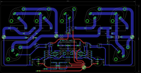
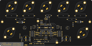
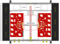
Here is the new PCB a friend laid out for me. Slightly larger than the original, but will be going into a custom cabinet in any case. I also have much larger heatsinks, and will be using two LT4320 cap-multiplier power supplies each with its own 160 VA toroidal. The new sinks being 150 mm high have roughly 5 times the radiating area of the originals. I may split them into two separate cabinets to place them just behind the speakers, but then the signal leads would have to be almost 3.5 metres long. I really don't want to build a balanced input circuit for this amp, but may end up doing it in the long run.
P.S. PCB 99% done by my best friend. Just needs the trimpots.
Hi gents,
Here is the new PCB a friend laid out for me. Slightly larger than the original, but will be going into a custom cabinet in any case. I also have much larger heatsinks, and will be using two LT4320 cap-multiplier power supplies each with its own 160 VA toroidal. The new sinks being 150 mm high have roughly 5 times the radiating area of the originals. I may split them into two separate cabinets to place them just behind the speakers, but then the signal leads would have to be almost 3.5 metres long. I really don't want to build a balanced input circuit for this amp, but may end up doing it in the long run.
P.S. PCB 99% done by my best friend. Just needs the trimpots.
Attachments
Last edited:
![Bedini_25_25[1].gif](https://www.diyaudio.com/community/data/attachments/826/826246-d8b31087a84cfb28a442bb0d7d9b7aa4.jpg "Bedini_25_25[1].gif")
![P1010422[1].JPG](https://www.diyaudio.com/community/data/attachments/826/826262-0fb85d3317f2311b42675ab1b7c3149e.jpg "P1010422[1].JPG")

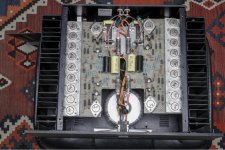
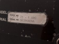
Hi all. Yesterday I have bought a Bedini 25 1 Meg to power my Quad ESL57, which reportedly seems to be a very good combination. First listenings were very pleasing and basically all good. What is disturbing me - the previous owner made several "improvements", mainly the original 110/120V transformer was taken out (thrown away!) and exchanged against a bigger toroidal transformer to fit to European 230V mains supply. Moreover, I assume as the inrush current saturation with the toroidal is much higher now, additional fuses have been added, with LEDs to show whether a fuse is blown, an LED indicating mains plug polarity and so forth... Also the front plate was mounted upside down (as the switch now collides with the big new transformer on the backside). I want to convert this all back to more or less original state, but I am missing the parameters for the secondary voltages (and amperes) of the original transformer (or transformers). I have a very qualified electronics service at hand, who has a proven capability to make custom transformers to my specs. So this should not be a problem, if I only knew, what the original transformers supplied (2x25V, 2x27V, other, what amperage?). Looking forward to help and feedback. I guess the infos above are already pointing in the right direction, but I am not sure whether the parameters would in the same way comply with the 1 Meg version of the Bedini 25. I also attached an image of the current state of the interior here. Looking forward to some feedback! Cheers, Markus
Attachments
Hi Markus,
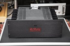
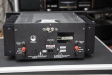
That is the Bedini 45/45 by the looks of it and not the 25.25, unless it is the 50/50 DE edition. Can you take a picture of the front and back panel and post them with the internal dimensions of the chassis. Also, measure the voltage out of the trafo please. I do not know the higher power amps (100/100 & BA-803) but I suspect the voltage on this one should be the same as the 25.25 at 2 x 20 V secondaries, as measured on the original E-core trafo. After rectifying that gives you 28 Volts. Drop me an e-mail (see your PM), and I'll send you what info I have.
That is the Bedini 45/45 by the looks of it and not the 25.25, unless it is the 50/50 DE edition. Can you take a picture of the front and back panel and post them with the internal dimensions of the chassis. Also, measure the voltage out of the trafo please. I do not know the higher power amps (100/100 & BA-803) but I suspect the voltage on this one should be the same as the 25.25 at 2 x 20 V secondaries, as measured on the original E-core trafo. After rectifying that gives you 28 Volts. Drop me an e-mail (see your PM), and I'll send you what info I have.
Last edited:
Bedini 25-1MEG more details
Thank you Ferret for your quick reply. I will post more images here. In fact I found several ads for amps claiming to be 25-1MEGs. Interestingly none of them looked the same ;-) I found only one image on Audio Asylum Trader where it clearly says "Bedini 25-1MEG" on the front of the device and this one has the similar front as mine. Inside measures are approx. 12,5x12,5x6,25 inch (32x32x16 cm). From what I know, the 1MEG option should result in a more powerful unit and better components, but I am not really sure what the difference to the "normal" Bedini 25/25 would be. I will measure the Transformer over the next few days and post the results here.
Thank you Ferret for your quick reply. I will post more images here. In fact I found several ads for amps claiming to be 25-1MEGs. Interestingly none of them looked the same ;-) I found only one image on Audio Asylum Trader where it clearly says "Bedini 25-1MEG" on the front of the device and this one has the similar front as mine. Inside measures are approx. 12,5x12,5x6,25 inch (32x32x16 cm). From what I know, the 1MEG option should result in a more powerful unit and better components, but I am not really sure what the difference to the "normal" Bedini 25/25 would be. I will measure the Transformer over the next few days and post the results here.
Attachments
Hi Markus,
This amp does not even appear on the Bedini website. According to some reading done on Audiogon and a few other forums, I get the impression that this is 25 W Class A, but with more output devices and a slightly lower biasing current; this to spread the load across more devices to provide a better bandwidth with a better damping factor. The theory is that it has an extremely flat frequency response from 1 Hz to 1 MHz.
You don't want to sell it do you?
Just joking, don't get rid of it - they are excellently made and designed amps. Will send you all the info I have.
Regards, Kevin
Bedini 25-1MEG Transformer Secondary - What is the correct value?
Meanwhile I have started to restore the Bedini to the original state. With its 2x 18V and 8.33A (230V mains) I get an output voltage of 12.6V and 1.54A current with a 440Hz sine signal at an input with 500mV gain. With this I calculate a power of approx. 19.4W. I also measure +/- 25V voltage after the rectifier. In the circuit diagram shown here in the thread you can see 2x 27V AC on the secondary side (instead of 2x18V at my Bedini). Now I don't want to just buy a transformer with 2x 27V secondary and try out what happens ... If someone has an idea how to proceed to determine the correct secondary voltage, that's very welcome!
Meanwhile I have started to restore the Bedini to the original state. With its 2x 18V and 8.33A (230V mains) I get an output voltage of 12.6V and 1.54A current with a 440Hz sine signal at an input with 500mV gain. With this I calculate a power of approx. 19.4W. I also measure +/- 25V voltage after the rectifier. In the circuit diagram shown here in the thread you can see 2x 27V AC on the secondary side (instead of 2x18V at my Bedini). Now I don't want to just buy a transformer with 2x 27V secondary and try out what happens ... If someone has an idea how to proceed to determine the correct secondary voltage, that's very welcome!
PCB Photos, strange caps
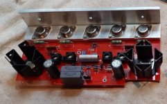
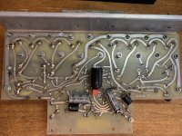
I detached successfully both PCBs and found marks identifying them as original 25/25 PCBs. On the backside they have three capacitors soldered which I do not find on the schematics (2x 100uF, 1x 1000uF). Does anyone know if these are original, or wether they have been added later on as an "optimization"?
I detached successfully both PCBs and found marks identifying them as original 25/25 PCBs. On the backside they have three capacitors soldered which I do not find on the schematics (2x 100uF, 1x 1000uF). Does anyone know if these are original, or wether they have been added later on as an "optimization"?
Attachments
Bedini
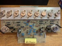
Not sure about the capacitors but it is definitely a 25/25 1 MEG because it uses the 2n5885 devices those were used exclusively in the 25 1 MEG. If it were a 45/45 or anything else it would use either a 2n3055 or a MJ15024 (or RCA 1b05 if its old enough). Before the 25/25 1 MEG it was called the 15/15 1 MEG which may be why you are getting 19 watts
The 1 MEG models (there was a 25 and a 100 watt version) were stable to 1 ohm
What happened since March?
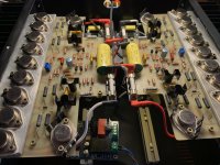
A few months have passed and I am still busy with my Bedini. Meanwhile I might have read every single bit of information that might be available about the Bedini amps on the internet. I also had to do some repairs. But first, here is a picture of the current state. At the front in the middle of the picture you can see an additional softstart module. I'm not sure I'll use it yet.
A few months have passed and I am still busy with my Bedini. Meanwhile I might have read every single bit of information that might be available about the Bedini amps on the internet. I also had to do some repairs. But first, here is a picture of the current state. At the front in the middle of the picture you can see an additional softstart module. I'm not sure I'll use it yet.
Attachments
Unfortunately the amplifier had problems with the DC offset, which was much too high on the left channel with approx. 124mV. But also on the right channel the DC offset was still very high with approx. 67mV. At first I continued to use the 18V secondary transformer, which generated approx. 24V rail voltage.
In addition, many of the blue resistors were very badly corroded on the leads, possibly due to a wrong flux. All of this meant that I changed most of the components bit by bit, including all the blue resistors on both channels.
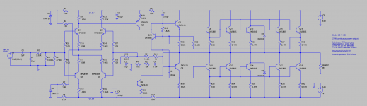
The current status of the amplifier is largely based on the BA2525 schematic that is available on the Internet. With two major exceptions. I have attached the exact schematic of my Bedini 25 1-MEG here.
In addition, many of the blue resistors were very badly corroded on the leads, possibly due to a wrong flux. All of this meant that I changed most of the components bit by bit, including all the blue resistors on both channels.
The current status of the amplifier is largely based on the BA2525 schematic that is available on the Internet. With two major exceptions. I have attached the exact schematic of my Bedini 25 1-MEG here.
Attachments
Last edited:
As you can see on the schematic, the Bedini 25 1-MEG uses eight 2N5885 per channel for current amplification instead of just four, as with the 25/25. At 0.47R, the emitter resistors are significantly larger than the 0.15R resistors on the BA2525 schematic. Another significant difference is the 1N4751 z-diodes for voltage stabilization, each in series with a 5K6 resistor. The rest is pretty much the same.
At full modulation with an input signal of 500mV and 1000Hz, a distortion factor of 0.015% is achieved with my device if the quiescent current is set to approx. 0.26A at R33. This corresponds to about 0.12V across the resistor, instead of 0.06V, as with the normal 25/25.
At full modulation with an input signal of 500mV and 1000Hz, a distortion factor of 0.015% is achieved with my device if the quiescent current is set to approx. 0.26A at R33. This corresponds to about 0.12V across the resistor, instead of 0.06V, as with the normal 25/25.
Last edited:
However, at higher rail voltages, the dc offset increases significantly on both channels.
After all defective and damaged parts have been replaced, the DC offset on both channels is almost identical, but only somewhat low at approx. 24V rail voltage with 38mV and 43mV. With a rail voltage of 33V the DC offset is again at 63mV and 68mV way to high.
It should be noted that the differential amplifiers have been completely renewed. Not only were all MPS8099 and MPS8599 transistors from 100 pieces each closely matched on hFE and Vbe, even the collector and emitter resistors were matched. At the moment I don't see what I could do to reduce the dc offset even further.
Regardless of which rail voltage is used, the output voltage at full level (500mV, 1kHz at the input) is now always around 12.6V - 12.8V at 8 Ohm, which corresponds to an output power of 20W, as opposed to the 25W the 25-1MEG should be able to generate. Or did I misunderstand something? In any case, the data sheet says that the Bedini 25/25 also generates 25W of power at 8 ohms, hence the name 25/25 ...
As WorriedInitial said earlier, there would also have been a 15/15 1-MEG, but in fact I have never heard about that amplifier and this would also indicate an output power of 15W, not 20W...
Last edited:
I'm not sure if the "missing" output power may be related to the z-diodes. My amplifier uses 1N4751 (30V breakdown voltage) instead of the 1N4742 (ZD12) with 12V breakdown voltage. According to my understanding, the 1N4751 would only stabilize the voltage as a z-diode when the rail voltage is above 30v (which again speaks for the 33V ...). But even then, the output voltage is still around 12.8V. Ultimately, I'm not sure whether this is the reason for the lack of performance at all.
If anyone here has any advice or a recommendation, I would be very happy. Ultimately, I am only missing about 1.5V output voltage to 25W. And still I am not sure if the 25 1-MEG was even intended to generate 25W output power...
If anyone here has any advice or a recommendation, I would be very happy. Ultimately, I am only missing about 1.5V output voltage to 25W. And still I am not sure if the 25 1-MEG was even intended to generate 25W output power...
- Home
- Amplifiers
- Solid State
- Bedini amp repair advice