This thread is to hopefully find ways to reduce distortion due to high frequency cross-conduction in current source driven power transistor Class-AB output stages.
An example of this problem is Wim de Jagger's "New Class-B" amplifier published in Electronics World December 1999 p982–7 A NEW CLASS-AB DESIGN
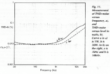
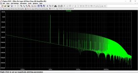
This new topology creates distortion from cross-conduction in the high end of the audio range. See Wim's Figure 11 (attached or view on my Gdrive - see my member info for link). Distortion is 0.1% at 20kHz. It rises steadily from 0.01% at 1kHz. Most of this distortion is from cross-conduction which is due to transistor charge storage because no base-emitter resistors are used and the bases of the power transistors are current driven. This unconventional approach solves the seemingly unsolvable thermal problems of Class-AB biasing stability, but instead we get more distortion from cross-conduction and more waste heat from cross-conduction.
Another example is described in Linear Audio Volume 13, "Current driven Output-stage class AB power amplifier" https://linearaudio.net/article-detail/2287. A different topology to Wim's but one that also drives the bases of the power transistors with current sources. There doesn't seem to be a colloquial term for this new type of Class-AB (see thread). I'll call it 'CSD' because it uses Current Source Driven power transistors, until someone comes up with a better one?
The Linear Audio 'CSD' amp gave 0.1% at 1kHz. Not good spec's for selling but to my ears it sounded as good as the Cube-law Class-A design with 30 times lower THD. Still, it would be nice if ways can be found to easily reduce the THD by removing most of the cross conduction; and that's the main aim for this thread.
Feel free to consider related things, like building a CSD amp, which can be done using a Bimodal PCB which is a Cube-law amp (Linear Audio Vol.8) but with CSD bipolar power transistors instead of lateral MOSFET's.
I have placed some LTspice simulation files on my Gdrive for anyone to use. The PDF 'BiModal-CSD+SqA-nsb' compares two 'nsb' methods. By adding a small square-law driver component to the linear driver current adds on 50% to the idle current but adds a true Class-A component extending to higher power levels and seems to mitigate distortion from cross-conduction") , but it doesn't do anything to reduce cross-conduction at high audio frequencies.
, but it doesn't do anything to reduce cross-conduction at high audio frequencies.
Simply adding base-emitter resistors for fast base charge removal wipes out current drive and brings back the thermal biasing stability to the standard output stage. Adding a current source instead of base resistors creates a sharp turn on/off at the start of the crossover region and this sounds worse than cross conduction distortion because it generates high order distortion. And adding a constant current from the drivers, like a non-switching class-B current, you are simply cancelling two constant current sources, so nothing gained. One idea that might help is a current mirror in a feedback loops with the power transistors. A jig is provided for download on my Gdrive as well. It can reduce cross-conduction dissipation but needs heavier frequency compensation, so no a lot of distortion reduction at the high frequency end.
These are a few starters. If you are bored by this technical stuff why not consider making a CSD amp, or a Cube-law amp. I'm avaiable to help DIYer's as much as I can. BTW these amps are not suitable for first time builders.
Ian Hegglun
An example of this problem is Wim de Jagger's "New Class-B" amplifier published in Electronics World December 1999 p982–7 A NEW CLASS-AB DESIGN
This new topology creates distortion from cross-conduction in the high end of the audio range. See Wim's Figure 11 (attached or view on my Gdrive - see my member info for link). Distortion is 0.1% at 20kHz. It rises steadily from 0.01% at 1kHz. Most of this distortion is from cross-conduction which is due to transistor charge storage because no base-emitter resistors are used and the bases of the power transistors are current driven. This unconventional approach solves the seemingly unsolvable thermal problems of Class-AB biasing stability, but instead we get more distortion from cross-conduction and more waste heat from cross-conduction.
Another example is described in Linear Audio Volume 13, "Current driven Output-stage class AB power amplifier" https://linearaudio.net/article-detail/2287. A different topology to Wim's but one that also drives the bases of the power transistors with current sources. There doesn't seem to be a colloquial term for this new type of Class-AB (see thread). I'll call it 'CSD' because it uses Current Source Driven power transistors, until someone comes up with a better one?
The Linear Audio 'CSD' amp gave 0.1% at 1kHz. Not good spec's for selling but to my ears it sounded as good as the Cube-law Class-A design with 30 times lower THD. Still, it would be nice if ways can be found to easily reduce the THD by removing most of the cross conduction; and that's the main aim for this thread.
Feel free to consider related things, like building a CSD amp, which can be done using a Bimodal PCB which is a Cube-law amp (Linear Audio Vol.8) but with CSD bipolar power transistors instead of lateral MOSFET's.
I have placed some LTspice simulation files on my Gdrive for anyone to use. The PDF 'BiModal-CSD+SqA-nsb' compares two 'nsb' methods. By adding a small square-law driver component to the linear driver current adds on 50% to the idle current but adds a true Class-A component extending to higher power levels and seems to mitigate distortion from cross-conduction
, but it doesn't do anything to reduce cross-conduction at high audio frequencies.Simply adding base-emitter resistors for fast base charge removal wipes out current drive and brings back the thermal biasing stability to the standard output stage. Adding a current source instead of base resistors creates a sharp turn on/off at the start of the crossover region and this sounds worse than cross conduction distortion because it generates high order distortion. And adding a constant current from the drivers, like a non-switching class-B current, you are simply cancelling two constant current sources, so nothing gained. One idea that might help is a current mirror in a feedback loops with the power transistors. A jig is provided for download on my Gdrive as well. It can reduce cross-conduction dissipation but needs heavier frequency compensation, so no a lot of distortion reduction at the high frequency end.
These are a few starters. If you are bored by this technical stuff why not consider making a CSD amp, or a Cube-law amp. I'm avaiable to help DIYer's as much as I can. BTW these amps are not suitable for first time builders.
Ian Hegglun
Attachments
This thread is to hopefully find ways to reduce distortion...
Hi Ian
I started a thread on current drive just a couple of months back, it's >Here<.
Jan Didden foreshadowed your article and I am very pleased to see you here in the forum, I look forward to more discussion.
Best wishes
David
Hi Ian
I started a thread on current drive just a couple of months back, it's >Here<.
Sorry, I missed seeing that.
Dave, your current-drive thread is a good one for general discussion on different ways to use current drive in transistor output stage. My thread is specific to reducing cross-conduction distortion in my output stage descried in Linear Audio Vol.13 ...
And my latest circuit can be viewed in my CDS Addendum (downloadable from my Gdrive), and you can run the Circuit in LTspice (download the BiModal Zip file).
In my opening post I mentioned making Linear Audio amps. But now I just noticed the existing Linear Audio Cube-amp thread is still active (thanks Jan Didden), so maybe it would be better to recommend that talk about making the Linear Audio amps take place in the existing Cube-amp thread.
That way we can concentrate on ways to get lower distortion from my output stage descried in Linear Audio Vol.13.
How's that sit to you?
And thanks for the welcome to the diyAudio community.
Cheers, Ian Hegglun
Hi Ian
Thanks for dropping in, as I am really interested in current driven current sources to be used as power amplifier, I will follow this thread closely.
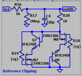
The second item of interest in your design is the way you implement soft clipping, as I am a strong belever of soft clipping I use one in my amplifier also.
The one I use is implemented with MosFet's but implemented differently, attached is a schema that I use. The MosFet's shown can be selected for exact 2VRMS or (when you do not like to discard most) in a range of 1.9...2.3VRMS (this gives about 50% keepers).
Best regards,
Frans.
Thanks for dropping in, as I am really interested in current driven current sources to be used as power amplifier, I will follow this thread closely.
The second item of interest in your design is the way you implement soft clipping, as I am a strong belever of soft clipping I use one in my amplifier also.
The one I use is implemented with MosFet's but implemented differently, attached is a schema that I use. The MosFet's shown can be selected for exact 2VRMS or (when you do not like to discard most) in a range of 1.9...2.3VRMS (this gives about 50% keepers).
Best regards,
Frans.
Attachments
I remember Wim de Jager's article from almost 20 yrs ago and remember thinking what an unusual design it was, more reminiscent of the internal architecture of an IC than a workable power amp.
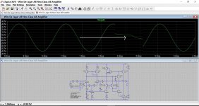
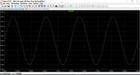
Curious, I just simulated the original and find I can not meet the original specs. In fact distortion is pretty obvious in the sim without even looking at FFT's or number crunching. It also seems very transistor (model) dependent.
I wonder if anyone ever built this design and is so what they thought of it.
Attachments
Some ideas could probably be lifted from this topology (with suitable adaptations, of course):
http://www.diyaudio.com/forums/solid-state/302358-does-anyone-recognise-topology.html#post4954495
http://www.diyaudio.com/forums/solid-state/302358-does-anyone-recognise-topology.html#post4954495
I remember Wim de Jager's article from almost 20 yrs ago and remember thinking what an unusual design it was, more reminiscent of the internal architecture of an IC than a workable power amp.
Curious, I just simulated the original and find I can not meet the original specs. In fact distortion is pretty obvious in the sim without even looking at FFT's or number crunching. It also seems very transistor (model) dependent.
I wonder if anyone ever built this design and is so what they thought of it.
This delay in switching off is what causes the cross-conduction that Ian referred to. I believe that's what he is looking to fix.
Jan
This delay in switching off is what causes the cross-conduction that Ian referred to. I believe that's what he is looking to fix.
Jan
With current drive the charge has no where to go especially when it wants to go in the wrong direction. I just got LA13 last night (thanks Jan) but do any of these circuits have bi-directional current drive? Quasi-saturation, etc. will give things like Mooly saw, visible distortion as the feedback can only go one way.
...
The second item of interest in your design is the way you implement soft clipping, as I am a strong belever of soft clipping I use one in my amplifier also.
The one I use is implemented with MosFet's but implemented differently, attached is a schema that I use. The MosFet's shown can be selected for exact 2VRMS or (when you do not like to discard most) in a range of 1.9...2.3VRMS (this gives about 50% keepers).
I'm pleased to find someone else who has developed an a soft clip circuit other than Bob Cordell's KleverKipper.
Can you share the circuit with suitable models for simulations? Or PM them?
BTW I found that my FET models needed quasisaturation added to the VDMOS (standard LTspice MOSFET) to get reasonably close simulations of soft clipping in my amps. I'd be happy to add quasisaturation to your models. You can view my quasisaturation model (developed with Keantoken's help) in my simulation of the CSD amp (Linear Audio Vol 13), eg file: BiModal-4v1-CSD....zip on my Gdrive.
Ian Hegglun
Curious, I just simulated the original and find I can not meet the original specs. In fact distortion is pretty obvious in the sim without even looking at FFT's or number crunching. It also seems very transistor (model) dependent.
I wonder if anyone ever built this design and is so what they thought of it.
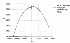
Your simulation shows up one of the weakness' of this topology -- the gain variation around the crossover region. I note you have used MJL21193/4 power transistors which are 4MHz, relatively slow compared to Wim's amp which used 2SA1095/2SC2585 which are 80MHz -- which makes a big difference in this topology, even at 1kHz.
This gain variation can be seen in Win de Jager's article Figure 3 (attached). This plot I assume is at a low frequency (1kHz or less) so cross-conduction current does not cause additional gain variations. Fig.3 variations in the crossover region are mainly from Beta differences in the driver and power transistors upper and lower halves.
The slow gain drooping is mainly from driver and power transistor Beta fall with current. Interesting, if you look at the earlier post showng Fig.11 distortion, the distortion does not increase as much with power as with frequency, showing large signal non-linearites are not the BIG problem in this topology.
And both p/n mismatch and Beta droop nonlinearities are much less significant in standard voltage drive output stages.
I never built Wim's amp but I did simulate it around 1999 when it came out.
Ian Hegglun
Attachments
With current drive the charge has no where to go especially when it wants to go in the wrong direction. I just got LA13 last night (thanks Jan) but do any of these circuits have bi-directional current drive? Quasi-saturation, etc. will give things like Mooly saw, visible distortion as the feedback can only go one way.
True the feedback can go only one way. The feedback has no way to make the transistor that is turning off to turn off faster to reduce distortion. Instead, the feedback makes the other transistor turn on more to get (close to) the right output voltage.
With current drive the charge has no where to go ... apart from getting used for continuing the base current until all the charge is dissipated by this internal current. The collector current fall off with current drive is relatively fast at first but has a long tail at the current levels used for the idle current. Even with 80MHz power transistors, like Win de Jager used the tail currents are still significant at 1kHz. Here's a quote from Win's EW article:
"The problem with power transistors driven by a current source is that there is no turn-off resistor for them. Under high frequency, high amplitude drive there will be a tendency for the effective bias current to rise dramatically.
By using HF power transistors with an fT of 80MHz, this bias current rise is reduced to 60% at 20kHz at full drive."
I'm hoping there's a way to increase the turn-off time under current drive without using 80MHz power transistors and without too much circuitary. Wim de jager would surely be interested too.By using HF power transistors with an fT of 80MHz, this bias current rise is reduced to 60% at 20kHz at full drive."
Ian Hegglun
Your simulation shows up one of the weakness' of this topology -- the gain variation around the crossover region. I note you have used MJL21193/4 power transistors which are 4MHz, relatively slow compared to Wim's amp which used 2SA1095/2SC2585 which are 80MHz -- which makes a big difference in this topology, even at 1kHz.
The above simulation was also using MJE243/253 drivers. Retaining the MJL21193/4 and switching to Bob C's MJE340/350 models and things look a bit better. Still 100ma bias.
Attachments
I'm pleased to find someone else who has developed an a soft clip circuit other than Bob Cordell's KleverKipper.
Can you share the circuit with suitable models for simulations? Or PM them?
BTW I found that my FET models needed quasisaturation added to the VDMOS (standard LTspice MOSFET) to get reasonably close simulations of soft clipping in my amps. I'd be happy to add quasisaturation to your models. You can view my quasisaturation model (developed with Keantoken's help) in my simulation of the CSD amp (Linear Audio Vol 13), eg file: BiModal-4v1-CSD....zip on my Gdrive.
Ian Hegglun
Here it is, one '.asc' sim-file and an picture showing (near) -200dB @ 1.4V input
Attachments
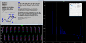
P.s. I do select mosfets by using a 10mA current source [as in the clipper] g and s are connected to each other (creating a 'mosdiode'), the Vds is measured. As stated before most ZVN3306's will be in the [useful] range of 1.8 to 2.3V
R16 can be lowered until the current delivered by Vin conflicts the maximum Ids of the MosFet (this will not very quickly happen, not many sources will deliver currents of 200mA and above)
The output of the clipper can be connected to a shunt potentiometer for volume control, or [in a balanced world] connected between the hot and cold clipper outputs.
Be sure to match all mosfets, 2 per unbalanced and 4 per balanced signal, thus in total 4 for unbalanced stereo and 8 for balanced
Last edited:
The above simulation was also using MJE243/253 drivers. Retaining the MJL21193/4 and switching to Bob C's MJE340/350 models and things look a bit better. Still 100ma bias.
Dear Mooly!
Please check my file,
however the results are similar like yours.
Attachments
- Status
- This old topic is closed. If you want to reopen this topic, contact a moderator using the "Report Post" button.
- Home
- Amplifiers
- Solid State
- Current-Source-Driven-power-transistors-and-mitigating-cross-conduction-distortion