Very Interesting
Certainly looks to be an interesting approach.
Currently I'm busy doing quite a few things including going back to work. Will download the files and investigate further.
BTW the IanHegglun article "Current driven Output-stage class AB power amplifier" in volume 13, linear audio magazine provides a good introduction to this subject. Quite an enjoyable read.
Hi All,
The circuit as shown is not buildable as is since different HV driver transistors are required for a 100W amp. But it wouldn't take much more work to finalise it and build one. It probably needs a new thread. Anyone interested in taking it up? I have enough to do already.
Certainly looks to be an interesting approach.
Currently I'm busy doing quite a few things including going back to work. Will download the files and investigate further.
BTW the IanHegglun article "Current driven Output-stage class AB power amplifier" in volume 13, linear audio magazine provides a good introduction to this subject. Quite an enjoyable read.
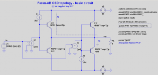
Simplified OPS showing the Faran-AB principle
Thanks Tibouchina for the like.")
To help see the principle clearly, what I call "Faran-AB", of paralleling two Faran-B stages and biasing one with sinking current and the other with sourcing current, I have a simplified output stage (which you can run) see attached.
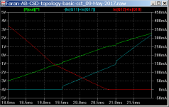
There's also a weighted THD file in the zip. It is useful because the THD readings are misleading. For example full output swing 100W/8R at 50Hz gives 2.4% THD (this is open loop) and wTHD is 50%. Reduce the power to 1W and THD is still 2.4%! But the wTHD is now 300%! -- so we have zero correlation of THD to wTHD in this case. If you look at the FFT plot of V(out) you can see why; the high order harmonics generated. A lot of nfb is still needed to make this OPS Hi-Fi -- just like most transistor amps.
But the advantage of Faran-AB is below a certain power you get low distortion once you get into the -A region. With 70mA bias this starts from 1W which is where music happens to be most of the time.
The other advantages are no need for an idle current trimpot plus no thermal instability in the power transistors and no need for power emitter resistors for paralleling. These have been top on the wish-list since transistor amps were first produced. A pity it has taken so long to find a way to do it.
And it is relatively simple and easy to implement as demonstrated in my previous post circuit for an amplifier.
Certainly looks to be an interesting approach.
... BTW the Ian Hegglun article "Current driven Output-stage class AB power amplifier" in volume 13, linear audio magazine provides a good introduction to this subject. Quite an enjoyable read.
Thanks Tibouchina for the like.
To help see the principle clearly, what I call "Faran-AB", of paralleling two Faran-B stages and biasing one with sinking current and the other with sourcing current, I have a simplified output stage (which you can run) see attached.
There's also a weighted THD file in the zip. It is useful because the THD readings are misleading. For example full output swing 100W/8R at 50Hz gives 2.4% THD (this is open loop) and wTHD is 50%. Reduce the power to 1W and THD is still 2.4%! But the wTHD is now 300%! -- so we have zero correlation of THD to wTHD in this case. If you look at the FFT plot of V(out) you can see why; the high order harmonics generated. A lot of nfb is still needed to make this OPS Hi-Fi -- just like most transistor amps.
But the advantage of Faran-AB is below a certain power you get low distortion once you get into the -A region. With 70mA bias this starts from 1W which is where music happens to be most of the time.
The other advantages are no need for an idle current trimpot plus no thermal instability in the power transistors and no need for power emitter resistors for paralleling. These have been top on the wish-list since transistor amps were first produced. A pity it has taken so long to find a way to do it.
And it is relatively simple and easy to implement as demonstrated in my previous post circuit for an amplifier.
Attachments
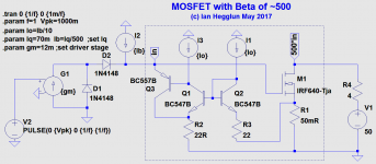
Faran-AB with power MOSFET's?
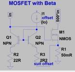
I'd like to extend Faran-AB to MOSFET's. Obviously we can't use current drive directly into the gates of MOSFET's, but if we add a current mirror to each MOSFET we can give it a 'Beta' (Hfe). See attached mirror circuit.
This could overcome the Spirito thermal instability problem (that occurs in linear mode) that makes most modern power MOSFET's unsuitable for audio amplifiers.
I'll try some simulations when I get a free day.
Thanks for that like.That is a neat idea, it naturally complements current drive.
I'd like to extend Faran-AB to MOSFET's. Obviously we can't use current drive directly into the gates of MOSFET's, but if we add a current mirror to each MOSFET we can give it a 'Beta' (Hfe). See attached mirror circuit.
This could overcome the Spirito thermal instability problem (that occurs in linear mode) that makes most modern power MOSFET's unsuitable for audio amplifiers.
I'll try some simulations when I get a free day.
Attachments
As far as I know, the Spirito stability factor applies to the way a given total current is distributed within the power MOSFET. You can fix the total current by good circuit design, but if due to local heating and operating at a low gate overdrive voltage eventually all current passes through a very small spot on the MOSFET, it will still be damaged.
Actually this is the very same phenomenon as thermal second breakdown in bipolar power transistors. When power MOSFETs first appeared on the market, the lack of second breakdown was their main selling point. Later the manufacturers started optimising their MOSFETs for extremely low on resistance and brought back the thermal stability problems in the process. High voltage MOSFETs are often still usable in saturation, especially when used at a much lower voltage than specified.
By the way, what power MOSFET designers call linear mode is precisely the region of operation that analogue integrated circuit designers do not call linear mode, but saturation: VDS >= VGS - Vth.
Last edited:
Some comments on your schematic there.
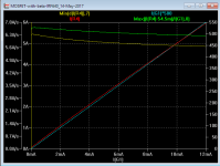
At 5A output of the MOSFET, the mirror will draw about 12mA. Re would be about 2.25R. This means a mirror draw of about 240uA for an idle bias of 100mA. At idle Re increases to 112R, much higher than your 22R degeneration. A 5x rise.
So I guess I1 will need to be not much under 10mA if you want the mirror to be relatively linear. Otherwise, the gain of the current mirror will rise at low currents, which I think would be bad for crossover.
Improved current mirror
See attached jig and plot. It is also very insensitive to Tj of the MOSFET at low currents. The jig is attached to check the temp co's.
Thanks keantoken. You are right. The Re of Q1 varies with Iin so it is a nonlinear mirror. Adding a PNP transistor to buffer Q1 and biasing Q1 with a constant current (same as Io) makes the effective Beta (Id/Iin) fairly linear.Some comments on your schematic there.
...At idle Re increases to 112R, much higher than your 22R degeneration. A 5x rise.
See attached jig and plot. It is also very insensitive to Tj of the MOSFET at low currents. The jig is attached to check the temp co's.
Attachments
Faran-AB with power MOSFET's demo
Hi All,
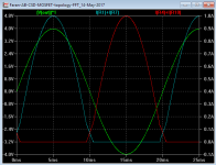
I have added drivers like the demo in post #120 and then an input stage. See attached circuit in 'Faran-AB-CSD-MOSFET-topology-FFT.zip'.
The crossover region is shown in the attached plot at 1W. Comparing the Faran-AB MOSFET version with the Bipolar version with the same input and driver stages and same idle current the weighted THD was about 1/5th at 1W 50Hz, eg 0.1% with MOSFET's (0.003% unweighted THD). This may be due to the 5 times higher Beta of the MOSFET's of 500.
Note this is with the gates of M1 and M2 shorted, likewise M3 and M4 gates shorted; no bias voltage generators are used. This the Faran-AB idea working with MOSFET's. There's no need for bias adjustment trimpot and the temperature sensitivity of the power MOSFET's is virtually zero. And small value source resistors are used.
Thermal instability problems of modern power MOSFET's is no removed since hot spots can form even if the MOSFET's drain current is controlled. MOSFET's that have a secondary breakdown like SOA plots suffer from hot-spots, but choosing higher voltage MOSFET's than needed for the rail-rail voltage helps to stay out of the secondary breakdown like region.
With a Faran-AB topology more power MOSFET's can be added in parallel without careful selection of threshold voltages by adding more mirror loops.
These simulations show a Hi-Fi Faran-AB amplifier is feasible. But no bench tests to report at this stage. These ideas can be used by anyone. First in first served. Let us know how you get on.
Cheers,
Ian Hegglun
...I'll try some simulations when I get a free day.
Hi All,
I have added drivers like the demo in post #120 and then an input stage. See attached circuit in 'Faran-AB-CSD-MOSFET-topology-FFT.zip'.
The crossover region is shown in the attached plot at 1W. Comparing the Faran-AB MOSFET version with the Bipolar version with the same input and driver stages and same idle current the weighted THD was about 1/5th at 1W 50Hz, eg 0.1% with MOSFET's (0.003% unweighted THD). This may be due to the 5 times higher Beta of the MOSFET's of 500.
Note this is with the gates of M1 and M2 shorted, likewise M3 and M4 gates shorted; no bias voltage generators are used. This the Faran-AB idea working with MOSFET's. There's no need for bias adjustment trimpot and the temperature sensitivity of the power MOSFET's is virtually zero. And small value source resistors are used.
Thermal instability problems of modern power MOSFET's is no removed since hot spots can form even if the MOSFET's drain current is controlled. MOSFET's that have a secondary breakdown like SOA plots suffer from hot-spots, but choosing higher voltage MOSFET's than needed for the rail-rail voltage helps to stay out of the secondary breakdown like region.
With a Faran-AB topology more power MOSFET's can be added in parallel without careful selection of threshold voltages by adding more mirror loops.
These simulations show a Hi-Fi Faran-AB amplifier is feasible. But no bench tests to report at this stage. These ideas can be used by anyone. First in first served. Let us know how you get on.
Cheers,
Ian Hegglun
Attachments
Last edited:
Finalised improved charge pull-out circuit for the LA-CSD amp
Attached are the promised simulation files for the improved charge pull-out circuit for the Linear Audio CSD amp. The circuit is for the BiModal 4v1 PCB which allows either the revised LA Cube amp or this LA CSD amp to be made on the same PCB. I just have started assembling the PCB.
The THD has been checked at 333Hz 8W into 8R and is 0.1% which is the same as the original circuit without the extra charge pull-out parts. I can't test THD at 20kHz.
BTW the THD reduced by half when I changed the input stage IC. This confirms that p/n asymmetry of the input stage FET's are mainly responsible for the mid frequency THD reading (as suggested in the Linear Audio Vol. 13 article) because the 2nd harmonic dominates. The mid frequency THD can be trimmed lower if required to 0.03% (below soft clipping) which is about same as the LA Vol. 8 Cube amp, and ther's no high order distortion in this CSD amp, just like the LA Cube amp.
To trim out the 2nd harmonic either by shunt R29 or add a few ohms to R28 while watching the FFT at say 8W at 1kHz.
Hi All,...For my bench tests I used the values shown and the idle current increased from 80mA to 120mA with no load and full swing square wave up to 130kHz (the limit of my oscillator). This is what I have been looking for. Simple and effective and no extra rail voltages.
I hope to do some THD tests. When I am happy all's well with this idea I'll post the full simulation circuit.
Attached are the promised simulation files for the improved charge pull-out circuit for the Linear Audio CSD amp. The circuit is for the BiModal 4v1 PCB which allows either the revised LA Cube amp or this LA CSD amp to be made on the same PCB. I just have started assembling the PCB.
The THD has been checked at 333Hz 8W into 8R and is 0.1% which is the same as the original circuit without the extra charge pull-out parts. I can't test THD at 20kHz.
BTW the THD reduced by half when I changed the input stage IC. This confirms that p/n asymmetry of the input stage FET's are mainly responsible for the mid frequency THD reading (as suggested in the Linear Audio Vol. 13 article) because the 2nd harmonic dominates. The mid frequency THD can be trimmed lower if required to 0.03% (below soft clipping) which is about same as the LA Vol. 8 Cube amp, and ther's no high order distortion in this CSD amp, just like the LA Cube amp.
To trim out the 2nd harmonic either by shunt R29 or add a few ohms to R28 while watching the FFT at say 8W at 1kHz.
Attachments
Last edited:
Highlights of this thread so far
Hi All,
A few highlights of this thread. This thread was originally started to overcome cross-conduction in the Linear Audio CSD amp here. Now that a simple modification has been found I'll start a new thread on a PCB maybe in a few months. For new comers, A CSD amp uses Current Source Driven power transistors which eliminates temperature effects on Class-AB optimum biasing and paralleling of power transistors does not use power emitter resistors.
I'd like to thank all who have contributed. Thanks to Jan Didden for helping me get started on diyAudio.com. Sorry I haven't been able to respond to you all.
This thread covers 4 topics! The highlights:
1. The highlight for a simple add-on circuit to the Current Source Driven (CSD) amp is post #107 (p11). The updated CSD amp circuit and simulation files are available in post #129 (p13). With these mods the amp does not suffer from high dissipation from cross-conduction.
2. The highlight for the de Jager topology is Post #60 (p6). For newcomer's the de Jager topology is the 'A new Class-AB design' in EW Dec 1999 here. BTW Keantoken PM'ed me to say a further modification reduced the simulated distortion at 20kHz by a factor of 60 but details haven't been shared. Maybe we will see a new thread for his mods.
3a. Two highlight for the Faran topology, the first is Post #122 (p13). For newcomer's the Faran topology is from a 1961 article by Faran & Falks 'High Impedance Drive …' first mentioned in Post #90 (p9) and the article is available on myDrive here. This post shows how to add idle current to the Faran-B amp to make it Class-AB without using and Vbe bias voltage generators and no trimpots to set the idle current. And there's still virtually no effect from junction temperature changes in the the power transistors. An amp simulation using this new idea is on myDrive here. This topology does not suffer from any cross-conduction.
3b. The second highlight for the Faran topology is Post #128 (p13) which uses current driven power MOSFET's. MOSFET's can't be current driven like Bipolar Transistors (BJT's) because they are voltage controlled devices so a current mirror is added to each MOSFET to make them behave like Bipolar Transistor's with a current gain.
By using the new Faran-AB mod (Post #122) we get yet another new type of MOSFET Class-AB where the idle current is defined without using and Vbe bias voltage generators, no trimpots to set the idle current and virtually no effect from junction temperature changes in the the power MOSFET's. The circuit for simulations using IRFP540/IRFP9640's is available in post #128 or myDrive in the diyAudio folder here. This topology does not suffer from any cross-conduction.
4. The 4th topic was on soft clipping circuits and their simulation.
Thanks again, I couldn't have done this without you all!
Hi All,
A few highlights of this thread. This thread was originally started to overcome cross-conduction in the Linear Audio CSD amp here. Now that a simple modification has been found I'll start a new thread on a PCB maybe in a few months. For new comers, A CSD amp uses Current Source Driven power transistors which eliminates temperature effects on Class-AB optimum biasing and paralleling of power transistors does not use power emitter resistors.
I'd like to thank all who have contributed. Thanks to Jan Didden for helping me get started on diyAudio.com. Sorry I haven't been able to respond to you all.
This thread covers 4 topics! The highlights:
1. The highlight for a simple add-on circuit to the Current Source Driven (CSD) amp is post #107 (p11). The updated CSD amp circuit and simulation files are available in post #129 (p13). With these mods the amp does not suffer from high dissipation from cross-conduction.
2. The highlight for the de Jager topology is Post #60 (p6). For newcomer's the de Jager topology is the 'A new Class-AB design' in EW Dec 1999 here. BTW Keantoken PM'ed me to say a further modification reduced the simulated distortion at 20kHz by a factor of 60 but details haven't been shared. Maybe we will see a new thread for his mods.
3a. Two highlight for the Faran topology, the first is Post #122 (p13). For newcomer's the Faran topology is from a 1961 article by Faran & Falks 'High Impedance Drive …' first mentioned in Post #90 (p9) and the article is available on myDrive here. This post shows how to add idle current to the Faran-B amp to make it Class-AB without using and Vbe bias voltage generators and no trimpots to set the idle current. And there's still virtually no effect from junction temperature changes in the the power transistors. An amp simulation using this new idea is on myDrive here. This topology does not suffer from any cross-conduction.
3b. The second highlight for the Faran topology is Post #128 (p13) which uses current driven power MOSFET's. MOSFET's can't be current driven like Bipolar Transistors (BJT's) because they are voltage controlled devices so a current mirror is added to each MOSFET to make them behave like Bipolar Transistor's with a current gain
. By using the new Faran-AB mod (Post #122) we get yet another new type of MOSFET Class-AB where the idle current is defined without using and Vbe bias voltage generators, no trimpots to set the idle current and virtually no effect from junction temperature changes in the the power MOSFET's. The circuit for simulations using IRFP540/IRFP9640's is available in post #128 or myDrive in the diyAudio folder here. This topology does not suffer from any cross-conduction.
4. The 4th topic was on soft clipping circuits and their simulation.
Thanks again, I couldn't have done this without you all!
Last edited:
- Status
- This old topic is closed. If you want to reopen this topic, contact a moderator using the "Report Post" button.
- Home
- Amplifiers
- Solid State
- Current-Source-Driven-power-transistors-and-mitigating-cross-conduction-distortion