Now that I have a working simulation I will try to analyse the circuit. (Here I do welcome specialist guidance).
Input transistors bases are connected together and referenced to GND so biasing is done by the bootstraps that feed the emitters of the input bgt.
For the negative pnp Q2 we have R9 and R10 bootstrap that feeds a voltage to Q2 emitter trough current limiting R12.
D2 seems to be used to compensate for temp variations on IPS.
For the positive npn Q1 we have the same arrangement trough R14 R15 R16 and D4.
IPS transistors are wired as common emitters so they provide voltage amplification with phase inversion. Gain is set by the ratio between collector and emitter resistors (R7 and R8 in the positive side).
For the positive side Q1, amplified signal comes from the collector that enters the base of Q3 (another common emitter).
Then follows a cascode Q6 that feeds the mirror responsible by transmiting the current to the voltage spreader that sets bias on the OPS.
The OPS uses medium power bjt for driving the output lateral mosfets.
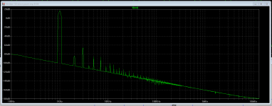
As initial diagram does not indicate the value for the GND feedback resistor R4, I set it to 400ohm so to have 26dB gain (closed loop).
The distortion is predominantly odd (3rd 5th and 7th)
I welcome expert imput on how to mitigate this... I would like to have more open loop gain so I could increase FB and lower overall distortion.
The distortion is predominantly odd (3rd 5th and 7th)
I welcome expert imput on how to mitigate this... I would like to have more open loop gain so I could increase FB and lower overall distortion.
Attachments
As initial diagram does not indicate the value for the GND feedback resistor R4, I set it to 400ohm so to have 26dB gain (closed loop).
The distortion is predominantly odd (3rd 5th and 7th)
I welcome expert imput on how to mitigate this... I would like to have more open loop gain so I could increase FB and lower overall distortion.
Hi RC,
To which plot is better to determine distortion? Can it be concluded in a simple transient run or the 2 tone IMD test? To me from the posted image you have more dBs from the fundamental 3rd 5th and 7th. My knowledge was the 2nd harmonic should have the highest dB percentage for an amp to sound "musical" the higher order harmonics should have the least dB [said to be machine tone].
Sa muli,
Albert
[BTW not an expert here
") ]
]It seems this type of symmetrical amp tend to strongly cancel 1st order harmonics.
I would like to reduce THD but need to find the best way to modify gain.... did not have enough enlightenment until now...
From what I have read from the experts, a higher open loop gain can indeed make the circuit linear thereby reducing distortion. when plotting the open loop gain, a current and voltage is inserted in the feedback loop. From this point of view perhaps you may want to work on voltages and currents, specifically. This could also sacrifice your closed loop gain, another factor is the topology used I do think some do have inherent low open loop gain [CFP for example]
Try increasing currents on your LTP, Biasing and especially VAS for this stage is where the "band cutting and "current pushing" needs more attention. Just be careful not to disturb the dc offset. This may need more careful work, make sure that the changes made does not make your LTP balance back to where it was for if it was happening that way, the changes goes nowhere. I learnt it from D. Selfs book.
Hope I could help you more.
- Home
- Amplifiers
- Solid State
- Meridian 103 clone