Yes, sure. I supposed those are written in Vietnamese language. Would you kindly please translate and share some contents?")
Clone projects that have been performed as long long time, so hard to tell you what we did by single post.
To success you must follow as:
1. Correct schematic
2. Correct components.
3. Correct layout design.
We performed clone Telos models, not use Mimesis (it just for reference). In first time, we have troubles with the oscillation. Goldmund quite easy to osc.
Just a remark about the Vietnamese Telos clone. I was lucky enough to purchase a kit of the Telos clone and it has performed very well indeed here ever since. I have not had the opportunity to compare it sound wise with a Mimesis clone, but maybe this Wiki will lead to me building one ;-)
Telos sound better Mimesis, more detail.
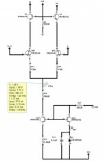
LTP's CCS of Telos creates approximately 4.6mA for tail current, this current will be shared by two LTP sides. Load of LTP is 1k5.
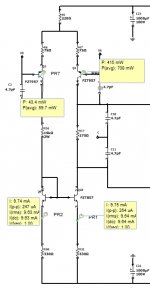
VAS use FZT857 and FZT957, they are complementary SOT223. It run quite low current than Mimesis, only 7.7mA per both side.
LTP's CCS of Telos creates approximately 4.6mA for tail current, this current will be shared by two LTP sides. Load of LTP is 1k5.
VAS use FZT857 and FZT957, they are complementary SOT223. It run quite low current than Mimesis, only 7.7mA per both side.
Telos sound better Mimesis, more detail.
LTP's CCS of Telos creates approximately 4.6mA for tail current, this current will be shared by two LTP sides. Load of LTP is 1k5.
VAS use FZT857 and FZT957, they are complementary SOT223. It run quite low current than Mimesis, only 7.7mA per both side.
Hi,
Walkalone, thank you for your information. Added to wiki.
The big forum you mentioned is AVVientnam?
Could you give us some name so that we can make research?
Best,
Eric
I found I am wrong. It's not DIP-24, looks like IDIP-24. Anyone knows?
It is a DIP 24 with the following specification: Row to Row Distance 15.24mm,
Pitch 2.54mm.
Hope this helps
It is a DIP 24 with the following specification: Row to Row Distance 15.24mm,
Pitch 2.54mm.
Hope this helps
Yes, my fault. It's DIP-24.
Thank you.
Yes, they are the same.
Hi keantoken,
What is your latest mod schematic? You mind share with us here?
best,
Eric


Hi!
I am building this Goldmund'ish clone, MP150 and I wonder if anyone has any experience with it?
As far as I know, MP150 is a product of Taiwanese DIYers community.
The schematic you posted, I think, is way too different from Goldmund.
But, still you can enjoy it.
Maybe I will putt my 5 cents here. I have build a several mosfet amplifiers with popular renesas latfets and after driving them from emitter follower all was good until I have mountet PCB's inside enclosure. The EF driver stage must be compensated so one additional resistor and one additional to92 transistor is not a big cost for the full thermal stability.
After latfet amp with EF driver stage is placed inside enclosure the temperaturre bias drift is really noticable (in my case it was approx +30%).
So my advice is add one more resistor + one more transistor to the "Vbe" circuit to make the amplifier happy.
Regards
After latfet amp with EF driver stage is placed inside enclosure the temperaturre bias drift is really noticable (in my case it was approx +30%).
So my advice is add one more resistor + one more transistor to the "Vbe" circuit to make the amplifier happy.
Regards
By"way too different" do you mean mainly topology or component values?
Thanks a lot for your opinions!
I mean the components and their values.
For example, MPSA42 is commonly used in Goldmunds.
Please review the wiki, there might be some differences, but also some in common.
MP-150
Thanks erikovsky!
In fact I'm using BC546/BC556 for the input stage and 2SA1013/2SC2383 for the second stage. The drivers are 2SA1930/2SC5171 and the outputs, though not having finally decided, could be 2SJ118/2SK413 or 2SJ200/2SK1529.
What du yoy think about using the Fairchild FQAs for output?

Thanks erikovsky!
In fact I'm using BC546/BC556 for the input stage and 2SA1013/2SC2383 for the second stage. The drivers are 2SA1930/2SC5171 and the outputs, though not having finally decided, could be 2SJ118/2SK413 or 2SJ200/2SK1529.
What du yoy think about using the Fairchild FQAs for output?
HiThanks erikovsky!
In fact I'm using BC546/BC556 for the input stage and 2SA1013/2SC2383 for the second stage. The drivers are 2SA1930/2SC5171 and the outputs, though not having finally decided, could be 2SJ118/2SK413 or 2SJ200/2SK1529.
What du yoy think about using the Fairchild FQAs for output?
View attachment 610625
Although 2SJ200/2SK1529 are nice mosfet designed for Audio their Audio signature is different than lateral mosfet (used in Goldmund amplifier). Also, Goldmund uses individual small bjt to drive each mosfet in the Telos. Lateral mosfet Do not require the same temperature compensation as vertical mosfet. Your amplifier may still be fine but could not be called a exact clone of the Goldmund...
Using FQA switching mosfet rather than mosfet designed for Audio may not be the wisest choice....
One other point is that the 2N5564 even though I Nice device has a very wide range of IDss current . Since sonority changes with operating current compared to IDss I wonder if Goldmund selected specific IDss devices ....for that reason I have used 2SK170 with operating current of about 70% of IDss in my Goldmund clone....
Fab
Last edited:
Thank for good input, fab!
Then I go for the 2SJ118/2SK413 for output. There are optional holes for 2SK170 on the PCB, so I could change the 2N5564 if I am not satisfied.
You are welcome . For clarification, I did not say that 2SJ118/2SK413 were better devices than 2SK1529/2SJ200...
I am confused if your pcb can also accept the pin out for lateral mosfet (source and drain are different compared to most vertical mosfet)... it seems so....thus you could also use Exicon lateral mosfet... if you use lateral mosfet you will have to lift the VBE transistor to prevent overcompensation of temperature....The layout does not seem to match the pcb for Q10 part...
With lateral mosfet you can also get rid of the source resistors...
Good luck
Fab
Last edited:
- Home
- Amplifiers
- Solid State
- Goldmund Wiki and build 2017