At least those voltages are reasonable although the L401 voltage should be close to zero.
Well you need to start somewhere...
Check the voltage across the Zener diode DZ401, it should be around 19 volts.
The voltage across R404 should be no higher than around 0.7volts, give or take.
Well you need to start somewhere...
Check the voltage across the Zener diode DZ401, it should be around 19 volts.
The voltage across R404 should be no higher than around 0.7volts, give or take.
Thanks for ur help ! No I need to buy those 4 fuses... don't know how but i did something wrong and i blow them up. Before that dz401 was aprox 19v and r404 around 9-10v.
Untill i find an open store(1-2 days) i wish u all "Happy New Year!" Have a nice party! Thanks again for your time !
Untill i find an open store(1-2 days) i wish u all "Happy New Year!" Have a nice party! Thanks again for your time !
You need to use a 'Bulb Tester' when fault finding which will limit current in the event of a fault. A 60 or 100 watt filament bulb in the mains live feed is perfect.
I have an amplifier test bed.
It uses crocodile clips for attaching power, input and speaker.
I also use a low power transformer (2 amps) in case of problems.
I power up amps without connecting to a speaker and if transformer hums i know there is a problem. I also monitor output on a scope and if voltage goes to either rail I know there is a problem.
I also have a speaker protector box in case the amplifier fails and outputs DC.
Must have saved me hundreds of £ in speakers over the years.
The high voltage on L401 shows that there is a major DC problem with the amp.
Q401 and Q402. The emitters are tied together on the diagram and so you might have mixed up E and B") but in any case the readings show a problem.
but in any case the readings show a problem.
What voltage do you have across R404. Your readings show -39 and -40 (so 1 volt from those figures) but we need to be certain and perhaps have a little more accuracy. If you actually do have 1 volt across the resistor then there could be a problem with Q403.
Lets see what is actually across that resistor though by placing the meter across it.
Q401 and Q402. The emitters are tied together on the diagram and so you might have mixed up E and B
but in any case the readings show a problem.What voltage do you have across R404. Your readings show -39 and -40 (so 1 volt from those figures) but we need to be certain and perhaps have a little more accuracy. If you actually do have 1 volt across the resistor then there could be a problem with Q403.
Lets see what is actually across that resistor though by placing the meter across it.
Roger that ! I'm taking B and E notation from the board. Sorry about that. Measured again with those results:
R404b -39,8/-41.2 v R404a -39.8/-40.4v
Q403b B-39.8/C38.8/E-41.2v Q403a B-39.8/C-1/E-40.4v
Q404b B39.2/C40.7/E38.7. Q404a B0.3/C0.9/E-1
b - broken channel
a - the channel that last time was working good
R404b -39,8/-41.2 v R404a -39.8/-40.4v
Q403b B-39.8/C38.8/E-41.2v Q403a B-39.8/C-1/E-40.4v
Q404b B39.2/C40.7/E38.7. Q404a B0.3/C0.9/E-1
b - broken channel
a - the channel that last time was working good
1.3 volt shows that transistor Q403 is faulty. The base/emitter junction should limit the forward voltage to around 0.6 to 0.7 volts just as a normal silicon diode would do.
If you compare the reading with the good channel you should see the difference.
The 2SC2229 is a high voltage type but with low current and power ratings.
HTTP 301 This page has been moved
Something like a 2N5551 should be OK to get it working but it has different pinouts.
If you compare the reading with the good channel you should see the difference.
The 2SC2229 is a high voltage type but with low current and power ratings.
HTTP 301 This page has been moved
Something like a 2N5551 should be OK to get it working but it has different pinouts.
Attachments
Ok. Back again. I've replaced it withe same transistor. Powered on, voltage on output channel dropped to 10v but in a few second it started to smell and smoke was coming out. Powered off. Q 403 was very hot. I've bought 2 so it's not a problem if u can find out what's happening. Another thing ... on this channel 2sc2235 was replaced with BD439. And Sb686/Sd617 on both channel were replaced with bd249c and bd250c. It worked a few years like that, but i've noticed right away the difference. I don't think that bd 249/250 are the right ones to use, but that's another discussion.
It sounds like there is a problem with the driver and/or output devices, that is possibly the reason for the original failure of Q403.
There is no way current should be able to flow 'back' from the output/driver stages to Q403 (and excess current is why the new one is getting hot).
What you need to do is this.
1/ Replace Q403 again. Be 100% certain you get the pinouts correct. What device did you end up using as replacements for this?
2/ R412 and 413 (47 ohm) need to be checked. Make sure they have not gone high in value.
3/ The two driver transistors should be checked to see if any show an obvious problem. I would recommend replacing these anyway but its good to find the fault rather than just change parts on spec.
4/ The two output transistors should also be checked and replaced if faulty.#
5/ Check the two 0.33 ohms and make sure they have not gone high or open circuit.
Connect a bulb tester to the mains input before powering on again. This will help protect against major failures in the event of a fault. A 100watt filament bulb in series with the live feed is all that is needed
6/ It is possible Q404 could have suffered if either of the upper pair of output or driver were faulty.
7/ Check the two 100 ohm resistors connected to the emitter of each driver.
Possible alternatives for the two drivers could be BD139 and BD140 (complementary pair) and MJL21193 and MJL21194 for the outputs.
First thing is to try and identify why Q403 was hot, and that can only really be failure of a driver and possibly an output as well.
The large output devices usually fail short circuit with little in between, drivers and other smaller devices can be leaky and suffer various failure modes.
Good morning !
So far i measured :
R412 / 413 - 47,1 / 47,1
R414 / 415 - 100 / 101
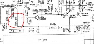
R416 / 417 - 0.8 / 0.9 - seems to be a problem here. Even if my tool is not so precise, it's still a big difference from 0.33
R416 / 417 are MPC71 0.33 5W . I'm thinking to replace them with https://www.adelaida.ro/r-5w-0r33-vertical-ax5wv-0r33.html.
After that i'll verify q404, q405, q406, q407,q408.
So far i measured :
R412 / 413 - 47,1 / 47,1
R414 / 415 - 100 / 101
R416 / 417 - 0.8 / 0.9 - seems to be a problem here. Even if my tool is not so precise, it's still a big difference from 0.33
R416 / 417 are MPC71 0.33 5W . I'm thinking to replace them with https://www.adelaida.ro/r-5w-0r33-vertical-ax5wv-0r33.html.
After that i'll verify q404, q405, q406, q407,q408.
Measuring very low value resistors needs a good meter and low resistance test leads. Firstly, whatever reading you get with the meter test leads shorted has to be subtracted from the reading. Thin test leads can easily have a few tenths of an ohm resistance.
Another good check would be to compare with the good channel.
Another good check would be to compare with the good channel.
- Status
- This old topic is closed. If you want to reopen this topic, contact a moderator using the "Report Post" button.
- Home
- Amplifiers
- Solid State
- Luxman L3 38VDC On Speaker Output?