Hello,
i believe that PNP is better than NPN. This is, because metals have positive charge, hence emitter and collector electrodes of a PNP transistor do not cause parasitic PN junctions. Datasheets tell, that PNP has better dynamics and stabler gain.
If we are gonna build stuff with PNP only, supply voltage will be negative, and ground will be topmost. Everything we plant will hang down, stabilized by gravity. We do not need much bracing and not feed back over more than two stages. Signals are catched up from and released into space using capacitors.
Starting with basic class-A:
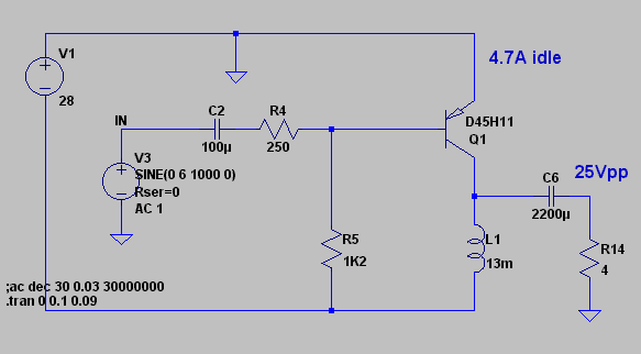
Maximum swing depends quite linearily on idle current. Idle power goes with idle current, but maximum output power goes with square of swing, so we go for maximum swing. 131 Watts loss for 20 Watts output is an efficiency of less than one sixth.
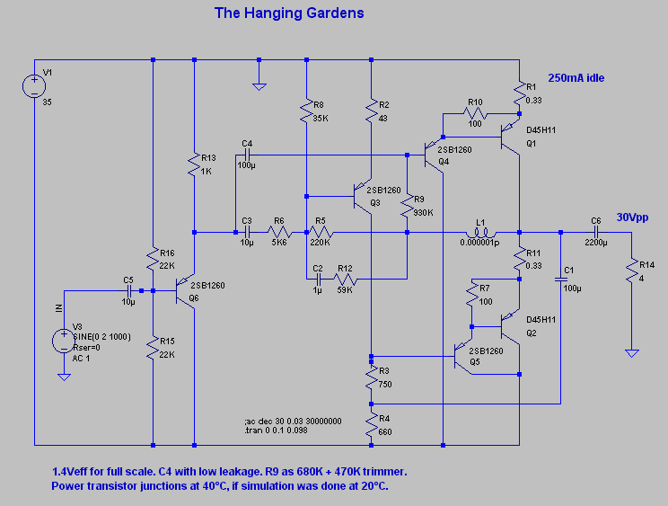
Now recalling Mister Hood's push-pull class-A scheme:

We have 2.4A idle current, which equals peak output current at a swing of 21Vpp. Rising idle current above this does not return enuf power gain, so we keep 2.4A idle current. Compared to single-ended above we have halved idle loss but also nearly output power.
Feeding back from collector to base lowered k2 and k3 but upset harmonic order. So i removed feedback.
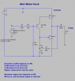
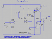
My genuine contribution is this:
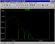
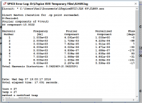
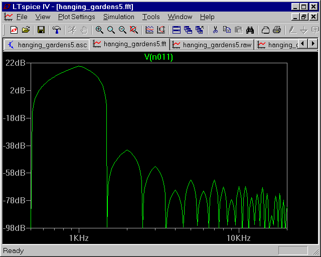
Power supply is raised to -35V, and idle current is much reduced. When power transistors have warmed up, idle loss will have reached 10 Watts (or 15 Watts, see below). In order to reduce crossover distortion i had to feed back. Distortion from -7dBW to 11dBW in 3dB steps, using 350mA idle current -- sorry, i do not want to redo the FFTs with 250mA:

I hope, that you can see the animated PNG. Firefox shows it, Opera does not. This nearly monotonous harmonic series may be a result of the topology, in which Q1 and Q4 are kept out of the feedback loop. Still their errors are corrected by the loop, after Mister Sandman's error take-off or Mister Walker's current dumping, which is a mild sort of error take-off. A guess would be, that one should not try to correct the sum of a push-pull arrangement by one feedback to both push and pull but only to one of them.
Uli
i believe that PNP is better than NPN. This is, because metals have positive charge, hence emitter and collector electrodes of a PNP transistor do not cause parasitic PN junctions. Datasheets tell, that PNP has better dynamics and stabler gain.
If we are gonna build stuff with PNP only, supply voltage will be negative, and ground will be topmost. Everything we plant will hang down, stabilized by gravity. We do not need much bracing and not feed back over more than two stages. Signals are catched up from and released into space using capacitors.
Starting with basic class-A:
Maximum swing depends quite linearily on idle current. Idle power goes with idle current, but maximum output power goes with square of swing, so we go for maximum swing. 131 Watts loss for 20 Watts output is an efficiency of less than one sixth.
Now recalling Mister Hood's push-pull class-A scheme:
We have 2.4A idle current, which equals peak output current at a swing of 21Vpp. Rising idle current above this does not return enuf power gain, so we keep 2.4A idle current. Compared to single-ended above we have halved idle loss but also nearly output power.
Feeding back from collector to base lowered k2 and k3 but upset harmonic order. So i removed feedback.
My genuine contribution is this:
Power supply is raised to -35V, and idle current is much reduced. When power transistors have warmed up, idle loss will have reached 10 Watts (or 15 Watts, see below). In order to reduce crossover distortion i had to feed back. Distortion from -7dBW to 11dBW in 3dB steps, using 350mA idle current -- sorry, i do not want to redo the FFTs with 250mA:
I hope, that you can see the animated PNG. Firefox shows it, Opera does not. This nearly monotonous harmonic series may be a result of the topology, in which Q1 and Q4 are kept out of the feedback loop. Still their errors are corrected by the loop, after Mister Sandman's error take-off or Mister Walker's current dumping, which is a mild sort of error take-off. A guess would be, that one should not try to correct the sum of a push-pull arrangement by one feedback to both push and pull but only to one of them.
Uli
Attachments

Last edited:
A half-baked circuit based on half based premises. Last time I checked, npns tended to be faster / more robust, with only a slight disadvantage in 1/f noise.
This output stage (a) is rather unbalanced in gain between the "push" and "pull" halves and (b) should generally not be expected to be performing well when transitioning to AB. No wonder distortion is awfully high. DC feedback does look a bit dubious indeed but would have to be simulated to be sure; still I don't think it would work out in practice.
There also is a PSRR elephant in the room, though you are not going to see that with an Rser=0 source...
Some tips for better FFT displays:
1. Use a decent window function, like Kaiser-Bessel, beta = 20.
2. Turn on the grid (Ctrl+G).
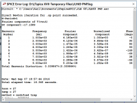
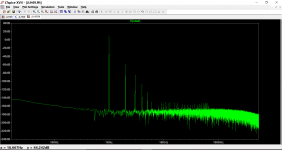
Thanks for the tip concerning FFTs, do you know what the second harmonic series tending to start to appear at 62 or 128 KHz is, Mister Grossklass?
Mona, these circuits will work, preferably with adjustment for actual current gain, which also rises somewhat with temperature.
X, just download the spice files and see what thou want!
Mona, these circuits will work, preferably with adjustment for actual current gain, which also rises somewhat with temperature.
X, just download the spice files and see what thou want!
Attachments
Interesting...
I tried this on the original JLH69. The PNP version seems to have a lower simulated THD. The bias current came out as very similar for both, around 1.2 amps.
I tried this on the original JLH69. The PNP version seems to have a lower simulated THD. The bias current came out as very similar for both, around 1.2 amps.
Attachments
Banat, it is a mind game with the following rules:
* Only PNP
* Feedback over only one voltage amplification stage
and goals:
* Try to archieve monotonously falling harmonic series (k3 softer than k2, and so on)
* Try to archieve low idle loss (several times lower than with class-A)
and the option to use a possibly helpful tool:
* Feedback loop does not include both push and pull but only either push or pull.
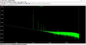
Mooly, i have done similar simulations, but my results are much worse. For one thing, most of the time i get a new harmonic series starting at 62 or 124 KHz. For another thing, i get too much k7 and k9: When i have a simple circuit with serious swing, i get high k7 and k9, which i can hardly reduce by feedback. Simulating a more complicated circuit with much feedback and reduced swing, k2 and k3 disappear, but k7 and k9 stay around -60 or -70dB. Actually feedback seems to introduce k7 and k9. My practical experience is, that most amplifiers have lo k7 and k9, at least i always thought so, so i am a bit confused.
* Only PNP
* Feedback over only one voltage amplification stage
and goals:
* Try to archieve monotonously falling harmonic series (k3 softer than k2, and so on)
* Try to archieve low idle loss (several times lower than with class-A)
and the option to use a possibly helpful tool:
* Feedback loop does not include both push and pull but only either push or pull.
Mooly, i have done similar simulations, but my results are much worse. For one thing, most of the time i get a new harmonic series starting at 62 or 124 KHz. For another thing, i get too much k7 and k9: When i have a simple circuit with serious swing, i get high k7 and k9, which i can hardly reduce by feedback. Simulating a more complicated circuit with much feedback and reduced swing, k2 and k3 disappear, but k7 and k9 stay around -60 or -70dB. Actually feedback seems to introduce k7 and k9. My practical experience is, that most amplifiers have lo k7 and k9, at least i always thought so, so i am a bit confused.
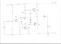
Turning Mister Hood's same-transistors push-pull class-A into AB by lowering bias results in inability to properly serve complex loads: Even with high load resistances there occurs an indentation in one flank.
Class-A has theoretical efficiency of 1/4, just like radiation coupling, say hornless loudspeakers and reflectorless senders. These devices are burdened with low efficiency and blessed with simplicity of design.
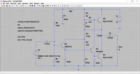
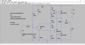
As i want to avoid class-A and an output transformer, i need at least one transistor complementing one other. While i am at compromising, i introduce another NPN in order to save a few parts:
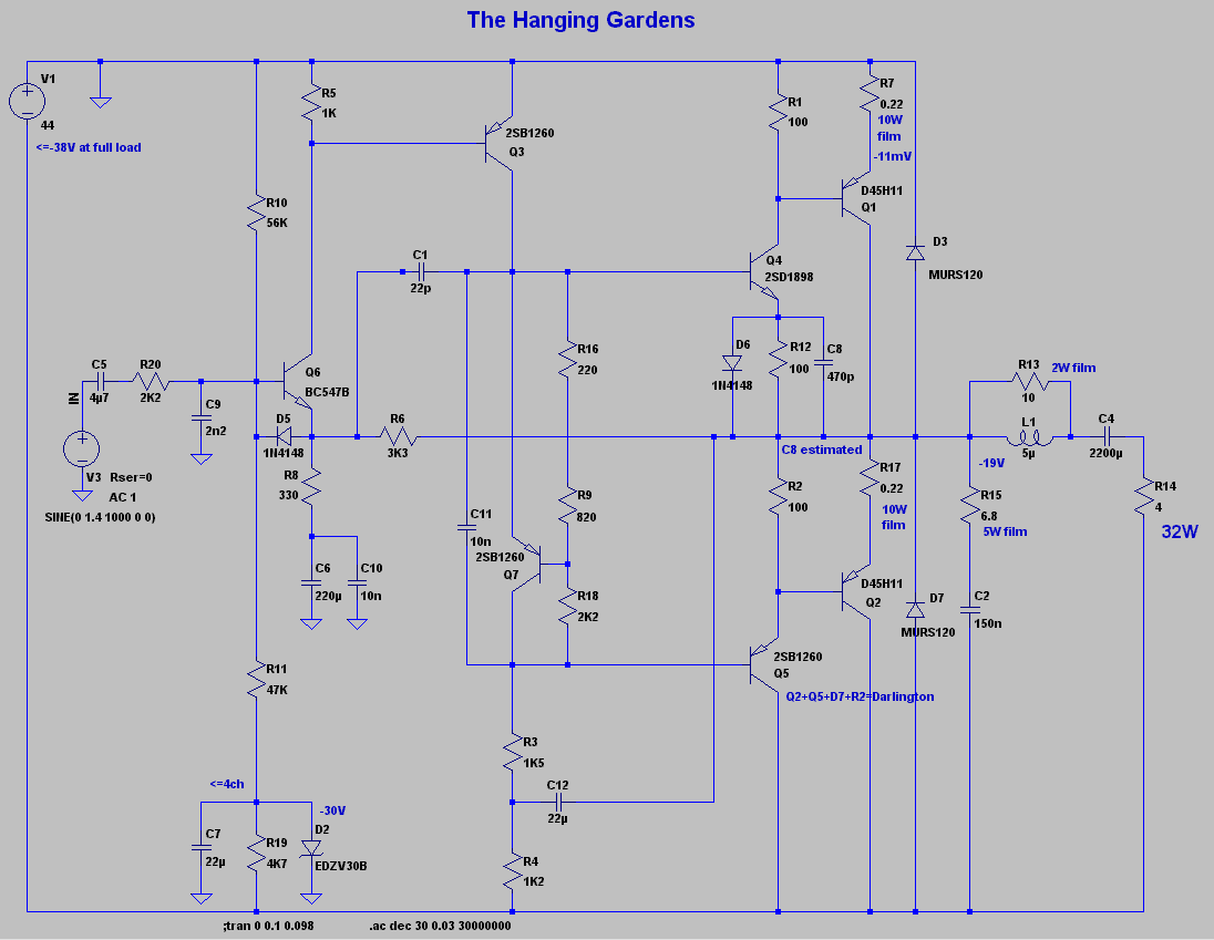
One should be able to statically overload it and feed it ultrasonic, for you know full-scale into input and a few Volts into output. Weather-proof comes at the expense of bandwidth being reduced to 31KHz and need for big film resistors.
This were at 50mA bias. Numbers were better, and assembling went faster, when using complementary Darlingtons.
Class-A has theoretical efficiency of 1/4, just like radiation coupling, say hornless loudspeakers and reflectorless senders. These devices are burdened with low efficiency and blessed with simplicity of design.
As i want to avoid class-A and an output transformer, i need at least one transistor complementing one other. While i am at compromising, i introduce another NPN in order to save a few parts:
One should be able to statically overload it and feed it ultrasonic, for you know full-scale into input and a few Volts into output. Weather-proof comes at the expense of bandwidth being reduced to 31KHz and need for big film resistors.
This were at 50mA bias. Numbers were better, and assembling went faster, when using complementary Darlingtons.
Attachments

Q4 and Q6, yes. It does not work any other way, if i want to avoid class-A or output transformer.
Still PNP is better than NPN, so power supply is negative, and i do not build a symmetry consisting of dozends of complements.
I might raise R8 to 1K and then have only one voltage amplification stage, since input stage will have inverting unity gain. Backdraw, i will need 3V~ input, tho this is rather easily gained by an additional voltage amplifier using one BC556B.
Last edited:
- Status
- This old topic is closed. If you want to reopen this topic, contact a moderator using the "Report Post" button.
- Home
- Amplifiers
- Solid State
- The Hanging Gardens