Let your mind roam free. Let your triply nested .STEP PARAM statements be wide-ranging. Copy Elvee's technique of putting three independent sources into the simulation, sinewaves whose frequencies are relatively prime, at three different positions in the circuit where unwanted ickynoise might be present. Then see which frequency(s) appear on the output.
To name one example of a random idea that spontaneously pops into a freely roaming mind: does anything good happen if you replace R5 with an Nchannel JFET like 2SK879 [datasheet attached]? Does anything bad happen?
Edit- now that I see jerluwoo's excellent post -- do you get any additional goodness if you replace his "R3" with an Nchannel JFET?
Attachments
Last edited:
I copied and moved the two models.text files to my LTspicefiles folder.
I opened the .asc
"run" but it can't find the models.
Where do I put the .txt files so that the .asc can find them?
I have to place them in the lib/sub directory for it to find them in my install.
Here is the model I have for tl431.
*Programmable Precision Reference pkg:TO-92 2,3,1. pkg: DIP8 6,1,8
.SUBCKT XTL431 2 3 1
*Reference input stage
Q1 3 1 10 QINPUT
RIN 10 2 500K
*Internal reference voltage
VR 20 2 DC 1.7791
RVR 20 2 1G
*Pole/Zero modeling
GM 0 30 10 20 1
RGM 30 0 1MEG
*Pole/Zeros: Pole 1= RGM & CP2, 10KHz
* Pole 2= RP2 & CP2, 60KHz
* Pole 3= CP1 & RZ1, 500KHz
CP1 30 40 15.9P
RZ1 40 0 20K
RP2 30 50 10MEG
CP2 50 0 0.265P
*Gain stage voltage clamp
DC 0 30 DCLAMP
*Output stage
GO 3 2 50 0 2.5U
DR 2 3 DNOM
.MODEL DNOM D(IS=100E-15 RS=7)
.MODEL DCLAMP D(IS=0.1)
.MODEL QINPUT NPN (BF=1 VAF=11.15)
.ENDS XTL431
Let your mind roam free. Let your triply nested .STEP PARAM statements be wide-ranging. Copy Elvee's technique of putting three independent sources into the simulation, sinewaves whose frequencies are relatively prime, at three different positions in the circuit where unwanted ickynoise might be present. Then see which frequency(s) appear on the output.
To name one example of a random idea that spontaneously pops into a freely roaming mind: does anything good happen if you replace R5 with an Nchannel JFET like 2SK879 [datasheet attached]? Does anything bad happen?
Edit- now that I see jerluwoo's excellent post -- do you get any additional goodness if you replace his "R3" with an Nchannel JFET?
Assuming you mean using the JFET to provide a constant current in place of the resistors, then yes there is benefit. However, the result is not better than the 2 JFET and needs more parts.
I will try finding some of Elvee's examples and see if I can't learn something from the way his simulations are set up.
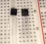
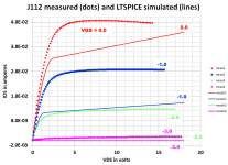
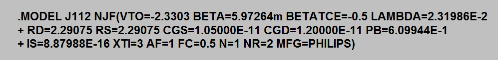
I started to do some measurements but quit early; went out to the pool for some sun and a T&T about half way thru. This is as far as I got. JFETs are notorious for their wide spread of parameters and maybe this might be a small piece of confirming evidence.
Attachments
Fairchild makes a low tempco version of the TL-431 called the KA-431. I use it in a CCS where the KA-431 sets the gate voltage of a power MOSFET. This is used as the cathode current sink in the output stage of a KT-120 PPP differential amp. At 300mA the bias current stays within +- 0.25mA cold to hot.
Although you won't see any improvement in sims with perfect dc rails, in a real world circuit with noise this can have a major improvement in psrr.
I use this CCS in my VSSA
")
Hi,
it´s always good if You can work with high values of the source resistor.
It reduces tolerances and increases impedance.
So I´m not at all convinced about ´audio´ JFETs like the SK170 as really good optimum choice for a ccs - at least in single fashion.
Heavily degenerated high Idss types are imho better here (if Youcan afford the loss in headroom due to their higher Vds/Vdg.
Things improve alot with a cascode and the 2N4393 and 2N4391 (or the MMBF/SMMT Variants) are excellent partners for SK170 or BF862.
Their low en of 3nV/sqr(Hz) isn´t bad either.
Btw. the output impedance of a current mirror source rises vastly by cascoding the output leg bipolar with a JFET or a depletion mode FET - similar to the cascoded JFET ccs.
jauu
Calvin
Hi!
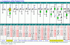
maybe I was not clear in post 12 with added link,
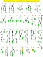
there are many ccs configurations which might have low niose, worth checking, the comparsions attached, I hope this will not rubbish the thread...
maybe I was not clear in post 12 with added link,
there are many ccs configurations which might have low niose, worth checking, the comparsions attached, I hope this will not rubbish the thread...
Attachments
Totally agree with Calvin.
One of the best low-noise CCS you can make, with low voltage headroom and high impedance is a heavily degenerated 2SK246.
Best to use Idss > 5mA (GR grade), and degenerate to < 2mA with a 1k to 1.5k resistor.
The high resistor value helps to stabilise against drift.
The current is almost independent on Vds as long as it is > 2V or so (= high dynamic impedance).
If you need more current then just put multiple in parallel.
Cascoding will improve dynamic impedance even further.
2SK170 and 2SK117 (=2SK209) do not appear to have as good a rejection for Vds variations.
The modern day equivalent for 2SK246 is 2SK208, available at Mouser.
http://www.diyaudio.com/forums/tubes-valves/226250-circuit-schematic-current-source-7-5ma.html
Patrick
Last edited:
bjt "ring of two" works to very low V
possibly useful fet info:
forum search titles in Solid State "ccs" gets earlier threads
looks good:
http://www.diyaudio.com/forums/solid-state/86626-searching-best-ccs.html
possibly useful fet info:
Siliconix jfet app notes from Archive.org JFETs Application notes
its useful to know the "triode/pentode" Vds operating regions
more on long/short channel fet and cascoding for ccs
forum search titles in Solid State "ccs" gets earlier threads
looks good:
http://www.diyaudio.com/forums/solid-state/86626-searching-best-ccs.html
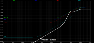
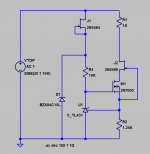
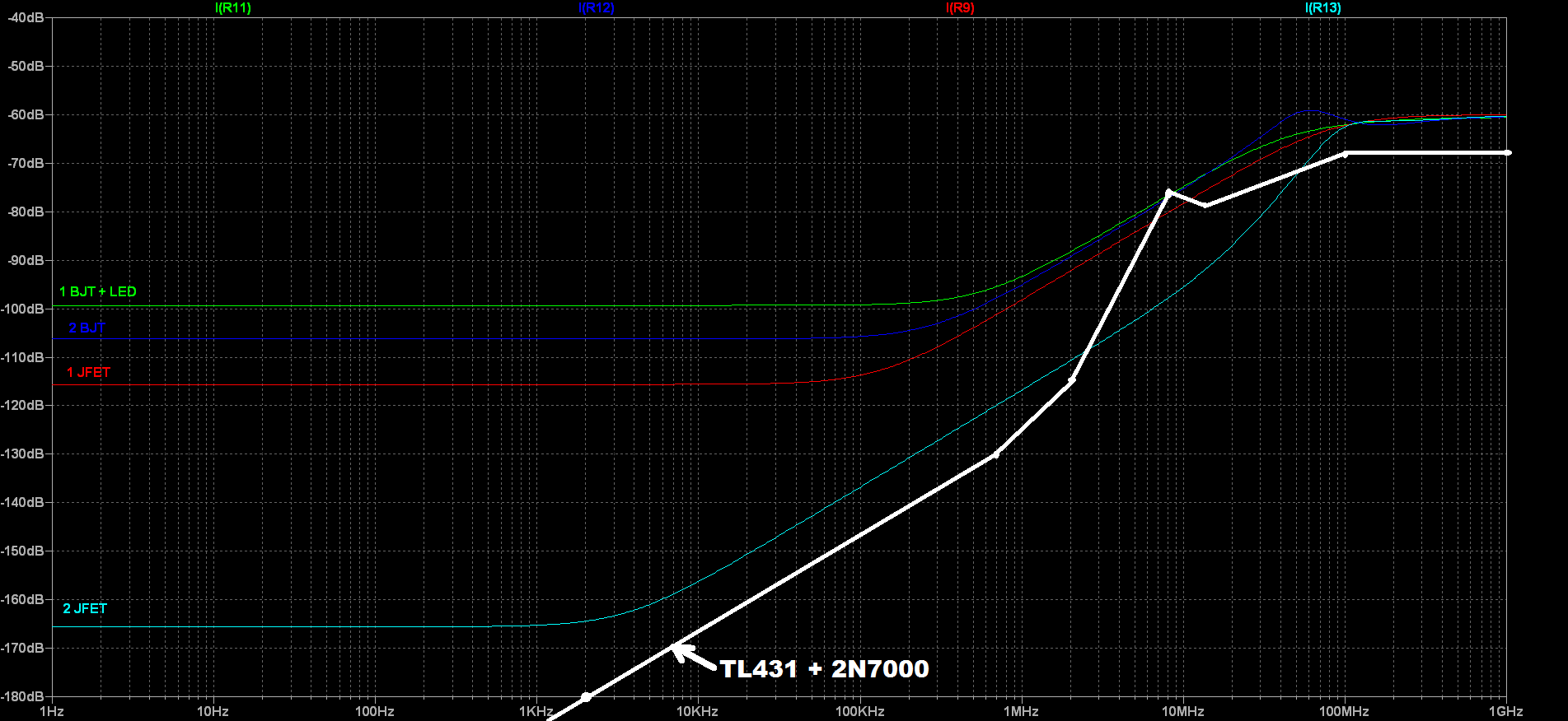
I used the subcircuit model of the TL431 in post#23, to build the current source shown below. I deliberately included the "flaw" of connecting the bias circuitry to the aggressor (noise source). Schematic and ac analysis in Figures 1 and 2 below. Figure 3 is my none too artistic attempt to overlay its frequency response, upon the chart found in post#1.
_
_
Attachments

Mark Johnson,
Thanks for presenting the quantitative gain of using various schemes such as LED+BJT, 2BJT, JFET, and TL431. The TL431 indeed looks very promising - can it provide that level of performance by itself or only when used in conjuction with ancilliary components as shown in the schematic with two JFETs and an n-channel MOSFET (a rather high parts count)?
Thanks for presenting the quantitative gain of using various schemes such as LED+BJT, 2BJT, JFET, and TL431. The TL431 indeed looks very promising - can it provide that level of performance by itself or only when used in conjuction with ancilliary components as shown in the schematic with two JFETs and an n-channel MOSFET (a rather high parts count)?
Experiment with these and see which design (or which design variation) you prefer. You might enjoy the current regulator diodes sold by Mouser.com; their parts count (1) is literally impossible to beat. Here is a link:
http://www.mouser.com/ProductDetail/Semitec/E-202/?qs=sGAEpiMZZMtQ8nqTKtFS%2fG7SPLwmKeGyXsvf6x3ETZ4%3d
I am not aware of any SPICE models for these devices; neither the manufacturer nor the DIY/hobbyist universe, seems to have fitted one.
http://www.mouser.com/ProductDetail/Semitec/E-202/?qs=sGAEpiMZZMtQ8nqTKtFS%2fG7SPLwmKeGyXsvf6x3ETZ4%3d
I am not aware of any SPICE models for these devices; neither the manufacturer nor the DIY/hobbyist universe, seems to have fitted one.
Last edited:
The TL431 circuit as shown is a 3-terminal device.
See also Fig.38 of datasheet for the two terminal version :
http://www.ti.com/lit/ds/symlink/tl431.pdf
I have used this many times as biasing current source for LDRs.
It is however not the lowest noise device you can come up with.
The advantage is of course current stability.
But you can also make much more precise CCS with quite low noise if you are prepared to go 3 terminal.
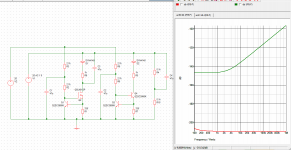
The attached Spice schematics is a circuit we used to match LDRs.
The requirement is stability over hours, and repeatability over months, rather than simplicity and low noise.
As an equipment current source it is hard to beat.
But it is unlikely I would use it in an audio circuit.
The E202 and the like are just JFETs with G & S connected together.
The dynamic impedance is not particularly good.
There are (were) equivalent devices from Central.
If I have to simulate then I just use the Spice files from Central.
Patrick
.
See also Fig.38 of datasheet for the two terminal version :
http://www.ti.com/lit/ds/symlink/tl431.pdf
I have used this many times as biasing current source for LDRs.
It is however not the lowest noise device you can come up with.
The advantage is of course current stability.
But you can also make much more precise CCS with quite low noise if you are prepared to go 3 terminal.
The attached Spice schematics is a circuit we used to match LDRs.
The requirement is stability over hours, and repeatability over months, rather than simplicity and low noise.
As an equipment current source it is hard to beat.
But it is unlikely I would use it in an audio circuit.
The E202 and the like are just JFETs with G & S connected together.
The dynamic impedance is not particularly good.
There are (were) equivalent devices from Central.
If I have to simulate then I just use the Spice files from Central.
Patrick
.
Attachments
Using an improved CCS is wholly dependent on the topology it is used in.
Ranging from a "blameless' , where the CCS's are working with NFB in both
the LTP/VAS.
To something like the Groner TIS .... where the TIS does all the ripple cancellation.
CCS type (or lack of one) , has little effect here.
Or , an ultra high feedback circuit (Sansui) , where global NFB rules. No CCS
still gets you >-100db PSRR.
OS
- Status
- This old topic is closed. If you want to reopen this topic, contact a moderator using the "Report Post" button.
- Home
- Amplifiers
- Solid State
- Constant Current Source (CCS) For Audio Applications