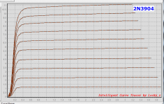
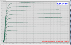
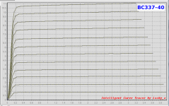
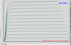
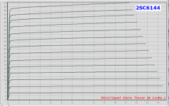
I've got an application in mind for an NPN bipolar, running about 10mA, at low VCE. Imagine a cascoded current source or a full 4T Wilson mirror, that sort of thing. I'd prefer to avoid transistors that exhibit Quasi Saturation at 10mA, because their effective ro (=Vearly/Ice) is poor.
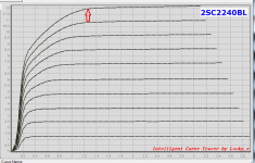
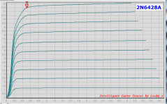
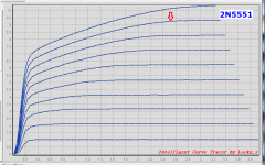
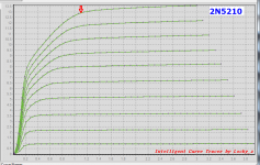
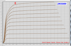
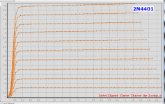
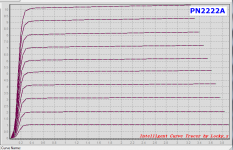
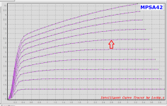
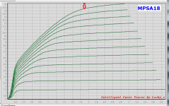
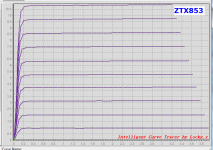
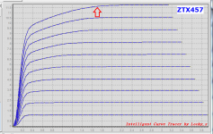
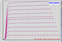
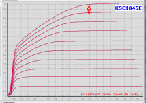
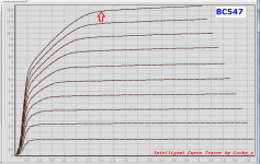
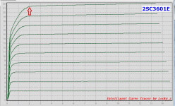
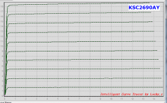
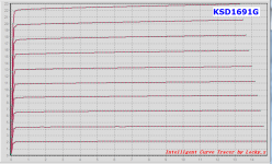
So I decided to measure a few transistors. Here are the results. The ones that my eyeball says "Yes, that looks like Quasi Saturation to me!!" are marked with red arrowheads.
Surprisingly, a few Author Favorite transistors seem to Quasi Saturate at 10mA:
So I decided to measure a few transistors. Here are the results. The ones that my eyeball says "Yes, that looks like Quasi Saturation to me!!" are marked with red arrowheads.
Surprisingly, a few Author Favorite transistors seem to Quasi Saturate at 10mA:
- Bob Cordell's preferred 2N5551: yes it Quasi Saturates.
- Douglas Self's 2SC2240BL and MPSA42: both Quasi Saturate.
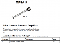
- Samuel Groner's MPSA18 (and 2SC2240BL): both Quasi Saturate.
Attachments
-
 2N3904.png31.1 KB · Views: 2,345
 -
 KSC945.png37.7 KB · Views: 942
 -
 BC33740.png27.9 KB · Views: 950
 -
 BC550.png38.3 KB · Views: 1,007
 -
 2SC2240BL.png35.6 KB · Views: 977
 -
 2N6428A.png33.8 KB · Views: 999
 -
 2N5551.png39.8 KB · Views: 2,322
 -
 2N5210.png39.1 KB · Views: 2,295
 -
 2N5089.png39.3 KB · Views: 2,294
 -
 2N4401.png31.4 KB · Views: 2,328
Different devices for different sockets, it's known as design. I wouldn't try to stand off 120V with a 2N4401 either. The cascode device, the one that sees the output swing has Vsat of 2 or 3V so what? Most PA's don't get anywhere near the rails on output swing.
Graph the Vsat at 10mA vs. collector-emitter breakdown this is a simple result of basic device physics.
Graph the Vsat at 10mA vs. collector-emitter breakdown this is a simple result of basic device physics.
Last edited:
I've got an application in mind for an NPN bipolar, running about 10mA, at low VCE. Imagine a cascoded current source or a full 4T Wilson mirror, that sort of thing. I'd prefer to avoid transistors that exhibit Quasi Saturation at 10mA, because their effective ro (=Vearly/Ice) is poor.
So I decided to measure a few transistors. Here are the results. The ones that my eyeball says "Yes, that looks like Quasi Saturation to me!!" are marked with red arrowheads.
Surprisingly, a few Author Favorite transistors seem to Quasi Saturate at 10mA:I don't mean to suggest that these fine gentlemen have made a mistake; rather, I'm just pointing out that when I run their favorite transistors at 10mA, the measured IV curves are a bit ugly. Perhaps these honorable fellows would never in ten million years recommend operating these devices at 10mA. I bet that in the future, they certainly do not.
- Bob Cordell's preferred 2N5551: yes it Quasi Saturates.
- Douglas Self's 2SC2240BL and MPSA42: both Quasi Saturate.
- Samuel Groner's MPSA18 (and 2SC2240BL): both Quasi Saturate.
Hi Mark,
Thanks for running these curves. We are always searching for better transistors for any given location in an audio amplifier. An example of where the 2N5551 might be used at 10mA might be the VAS or a pre-driver. These locations in an amplifier generally require a transistor with a rated voltage greater than 120V, since they have to withstand twice the rail voltage. High voltage transistors typically have more quasi-saturation effects at low voltage for a given amount of current as compared to transistors with only 40-60V breakdown. Most of the transistors that exhibited good quasi-saturation behavior in your tests were rated at less than about 60V.
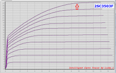
A nice transistor for the VAS or predriver is the 2SC3503, with 300V breakdown and 150MHz ft. However, its curves also exhibit quasi-saturation.
I'm very interested in knowing of VAS/predriver transistors that are better than the 2SC3503. It would be nice to have one with a breakdown of >150V, ft > 150 MHz, small Cbc, and minimal amount of quasi-saturation at 10mA.
Thanks again for this data.
Cheers,
Bob
Thanks for the measurements Mark. Are those curves at constant Ib?I've got an application in mind for an NPN bipolar, running about 10mA, at low VCE. Imagine a cascoded current source or a full 4T Wilson mirror, that sort of thing. I'd prefer to avoid transistors that exhibit Quasi Saturation at 10mA, because their effective ro (=Vearly/Ice) is poor.
If so, I'm not sure quasi-saturation is a problem in your application. There you effectively have 'constant Vbe' rather than constant Ib
Rohm 2SC2412 or repackaged equivalent?
Checking the datasheet the quasi region doesn't seem to be evident until much more current.
EDIT- the older copy of the datasheet has a chart for 0-10mA
The higher voltage 2SC4102 (or equivalent) datasheet seems to show evidence of quasi saturation in the regions of interest.
EDIT2-
How do 'switching' transistors like 2SC6099 perform in the region of interest?
Last edited:
Scott, the MPSA18 may be an unusual case. It's got a low datasheet breakdown voltage (45V) yet tons of quasi-saturation.
I sure do agree with the idea that the two series transistors in a cascode need not be the same device type / part number. But I very seldom see this in published schematics.
Stuartmp, yes these are lab measurements of actual, physical transistors. "Curve Tracer" (written in red at the bottom right of every image file) is the name of a specialized piece of equipment which plots the transfer function(s) of 2-terminal and 3-terminal components. Here is a Wikipedia article about curve tracers.
_
Attachments
If [those curves are at constant Ib] I'm not sure quasi-saturation is a problem in your application. There you effectively have 'constant Vbe' rather than constant Ib
You may be right! Although 'constant Vbe' depends on the output impedance of the bias network that drives the base. Let's run a little algebra on it.
When collector current Ic changes by fraction F (let's assume F = 10% = 0.10), base current (= (Ic/Beta)) changes by (F*Ic/Beta). Since the base drive circuit has finite impedance Z, the base voltage changes by (Z*F*Ic/Beta). We can equate this to the change in collector current, divided by transconductance gm:
- Z*F*Ic/Beta = F*Ic/gm
- thus Z/Beta = 1/gm
- and finally Z = Beta/gm
You may be right! Although 'constant Vbe' depends on the output impedance of the bias network that drives the base. Let's run a little algebra on it.
When collector current Ic changes by fraction F (let's assume F = 10% = 0.10), base current (= (Ic/Beta)) changes by (F*Ic/Beta). Since the base drive circuit has finite impedance Z, the base voltage changes by (Z*F*Ic/Beta). We can equate this to the change in collector current, divided by transconductance gm:Plugging in some representative numbers, at Ic=10mA we have gm = 0.38 siemens. If the transistor Beta is 200 we need the bias network's output impedance Z to be 526 ohms or less. In the very worst case, where a bypass capacitor to AC ground is the only low impedance path, to give 526 ohms at 5 Hertz (!), we will need a bypass capacitor of 61 microfarads or greater. This is not especially difficult except perhaps on teeny tiny surface mount daughterboards like discrete opamps fitted into small footprints.
- Z*F*Ic/Beta = F*Ic/gm
- thus Z/Beta = 1/gm
- and finally Z = Beta/gm
Hi Mark,
I think there are three things of interest to bear in mind.
It looks like you are assuming an undegenerated VAS transistor fed by a fairly high impedance. I always use a degenerated VAS preceded by an emitter follower (2 EF VAS). I usually degenerate by about 10:1. These two things tend to mitigate some of the effects we are talking about.
When using a cascode or similar type VAS, it is definitely a good idea to use different transistors for the VAS transistor and the cascode transistor. The former can be low voltage and have less quasi saturation, while the latter must be a high-voltage transistor.
Finally, the Wilson current mirror was designed in the context of linear integrated circuits, where the transistors are naturally well matched. In discrete implementations, especially where different types of transistors are used in different parts of the Wilson, some of its nice attributes will be lost.
Cheers,
Bob
Transistors wanted
As some of you know, I'm working on the second edition of my book. One of the things I'd like to do is to expand and bring up to date some of the transistors I am discussing. In perticular, I want really good transistors that can still be purchased.
Here are the kinds of your favorite candidates I want you to suggest:
1. Good IPS transistors in TO-92 packages that can handle at least 70V, have ft > 100 MHz, and have beta >100.
2. Good VAS and predriver transistors, likely in TO-126 packages, that can handle at least 130V, have ft > 100 MHz, and have beta > 100. The 2SC3503 meets these requirements, but I am interested in knowing of others, since availability of good discrete transistors can be spotty.
3. Good driver transistors, likely in TO-220 packages that have similar capabilities to those above, but with higher dissipation and SOA capability.
4. Good power transistors, likely in TO-247, TO-264 and MT-200 packages that have characteristics similar to, or better than, the MJL3281 and MJL1302.
Cheers,
Bob
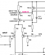
I am assuming a cascode current source like the attached, upside down using NPNs. diyAudio member kgrlee points out that, to the extent node "A" and node "X" are zero impedance voltage sources, the two BJTs operate with constant VBE rather than constant Ib. So I made a stab at calculating the worst case (largest possible) value of bypass capacitor from node X to the positive rail, which is necessary to make the impedance sufficiently low.It looks like you are assuming an undegenerated VAS transistor fed by a fairly high impedance
_
Attachments
Scott, the MPSA18 may be an unusual case. It's got a low datasheet breakdown voltage (45V) yet tons of quasi-saturation.
Never really explored that device. I just wanted to make the point that the quasi-sat is a necessary evil for many high voltage processes and every circuit position needs to be optimized. One handle is current density so a medium power 120V + device might be the best Vas choice. Did you look at any of those like the 2N3440 (old school)? A TO92 at 10mA and ~60 - 100V is marginal on PD in the first place.
more small signal NPNs @ 10mA
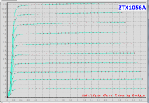
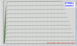
I had eight more NPNs in TO-92 packages. Turns out that three of them exhibit quasi saturation. Images attached.
(ZTX851 is the device called out in Art Of Electronics 3rd Edition, for its supremely low rbb (hence supremely low voltage noise) performance).
_
I had eight more NPNs in TO-92 packages. Turns out that three of them exhibit quasi saturation. Images attached.
(ZTX851 is the device called out in Art Of Electronics 3rd Edition, for its supremely low rbb (hence supremely low voltage noise) performance).
_
Attachments
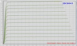
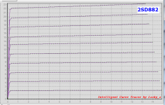
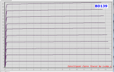
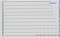
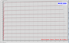
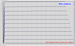
some medium- and high-current transistors
I measured some medium-power (TO-126) and high-power transistors (TO-220) to see whether they exhibited any quasi saturation. Only two of them did.
_
I measured some medium-power (TO-126) and high-power transistors (TO-220) to see whether they exhibited any quasi saturation. Only two of them did.
_
Attachments
(ZTX851 is the device called out in Art Of Electronics 3rd Edition, for its supremely low rbb (hence supremely low voltage noise) performance).
This all continues to make sense, design for extra low rbb ends up being more die area, sort of like a bunch of paralleled devices (see for instance the folklore around the LM3XX? matched pair). The current density is then low and Vcesat, etc. all benefit at a loss in speed due to higher parasitic capacitances and the fact that you operate away from peak ft in many cases.
If the application is the CCS for the LTP i/p of a power amp, I don't think you will gain much with fancy CCS versions.I am assuming a cascode current source like the attached, upside down using NPNs. diyAudio member kgrlee points out that, to the extent node "A" and node "X" are zero impedance voltage sources, the two BJTs operate with constant VBE rather than constant Ib. So I made a stab at calculating the worst case (largest possible) value of bypass capacitor from node X to the positive rail, which is necessary to make the impedance sufficiently low.
There's at most a couple of volts swing at the LTP so the CCS never gets near sat. More important to look at small (and not wonky) Ccb of the i/p transistors.
Besides if the CCS tail isn't 'perfect', it'll only introduce some nice 2nd harm. and there's so much feedback at very LF that I doubt you'll even see that

There's more reason in the CCS for a VAS but even then, the more complex CCSs take up another volt or so and you have very little return for the greater complexity. If you're lucky, you might get an extra 1dB in your power spec for supa dupa THD.
But 2sc3503f looks worrying with quasi-sat below Vce 10V, especially when used for the VAS
_____________________
On the subject of whether the VAS is fed by a current or a voltage, IIRC, I made a comprehensive study in my tpc-vs-tmc-vs-pure-cherry thread.
The answer is as expected, "it depends".
What does come out of that is driving the VAS with an emitter follower, ala Self, does feed it with a 'voltage'.
Apart from the expected extra gain, an important benefit is that the 'voltage' drive makes the wonky Ccb of the VAS much less important so a cascode VAS becomes unnecessary.
... design for extra low rbb ends up being more die area, sort of like a bunch of paralleled devices ... The current density is then low and Vcesat, etc. all benefit
Is this because you devote more top surface area to base contacts and their surrounds? Area which is stolen from emitter area? The ratio (total emitter area)/(total die area) goes down, and this is a rough approximation of current density?
Perhaps you also lay out the emitter fingers at their minimum possible width (min contact + 2*min_surround)? Then you lay out base contacts the full finger length, on both sides of each finger, to reduce the distance between the "active base" vertical region, and the base contact?
Base-emitter-base subassembly fingers would be stacked side by side like cigarettes in a box, with collector sinkers laid out parallel to the BEB fingers and placed every "N" fingers for the largest value of N you dared? An N which balances layout efficiency vs. collector resistance?
I can't imagine that a checkerboard layout of emitters and bases, with basket weave diagonal metallization of the base contacts and emitter contacts, would be as efficient. The 2D array of emitters would have less total area than the 1D array in the cigarette/finger approach.
- Home
- Amplifiers
- Solid State
- Looking for a small signal NPN with no Quasi Saturation: MEASURED DATA