Here is something interesting.
Yamaha A520 involves a classic RF Toko style transformer somewhere in the feedback and the bias Even though these transformers are adjustable nothing is written in the service manual about the procedure or the need of adjustment
Any bode cares to take a quick look at the schematic and explain ?
here is a snapshot of the detail and the complete schematic
Yamaha A-520 - Manual - Stereo Integrated Amplifier - HiFi Engine
Attachments
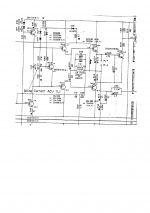
That s a two pole compensation, the inductance role is more than doubtfull, all it does it to keep the common point of the drivers emitter Resistance from being HF coupled to the output while it allow DC coupling..
I wonder if Yamaha didnt use this circuitry to mislead some eventual plagiarism, anyway if it work without oscillating there s nothing to trimm...
I wonder if Yamaha didnt use this circuitry to mislead some eventual plagiarism, anyway if it work without oscillating there s nothing to trimm...
Hi fellas!
I am wondering if any of you folks can tell me something about this amplifier. I can buy a unit in perfect cosmetic condition, but faulty right channel (makes a weird buzzing sound when it plays music) for $25. What can i expect from this amplifier? How can you describe it's sound signature?
I am wondering if any of you folks can tell me something about this amplifier. I can buy a unit in perfect cosmetic condition, but faulty right channel (makes a weird buzzing sound when it plays music) for $25. What can i expect from this amplifier? How can you describe it's sound signature?
- Status
- This old topic is closed. If you want to reopen this topic, contact a moderator using the "Report Post" button.