It's easier than one may think - getting old I guess.
Anyway, see attach.
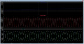
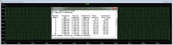
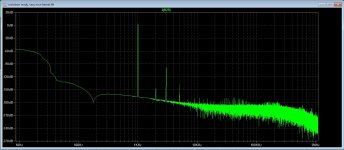
Sweep is done for Vac1..16V which translates into 28 Vpk at the load. No NFB though.
Well that is quite suprising because I did it that way also, but with one opamp, but with diodes you have not used, canceling of signals in circlotron reason? I was even thinking about using comparator and squarewave generation with rectifier diodes using it to generatie a pwm who adjust bias.
If you look at mine plots in previous post, you see the transition of the red output signal crossing the green and blue current line, when the current clips to zero voltage like the green or blue line this happens when the sinoidal signal is at max voltages, clearly are seen the crossings line when there is some couple hundreds of milliamps idle left, the idle current run out happens when transition through zero is already happened, and as such no crossover, did have low distortion. Do you now that the simplest things are the toughest.
Your way is interesting for keep it outside the amp stage itselfs, used for regulate current on reference resistors.
Your age? I do not now, but I am 62, and not so much experience with electronincs as you have, I have never had school for that, I did get to work when I was 14, and have learn shoemakers profession. electronics is hobby, I do now things afcouse, but the calculate things I do not now all, but LTspice do that for me, theory about amps I do read from books.
Now busy with house, putting laminate on the floor and remove the carpet, gives a lot better acoustic in the room.
thank you very much for the help and tips, I appreciate it.
You're correct. Peak detector/the whole circuit may be different. Used AD one just to check an idea.
Later
P.S. The circuit extracts the idle current per say, so an additional circuit needed to keep the former at a particular value.
As for the circlotron I do have a single ended driver section. this give some more dc at the outputstage itselfs on both ends, this cancels the offset voltage completely, I do not now if this 6 or more volts dependent of mosfets used can give trouble, even into that voltage is current present.
I can make the driver section with a negative voltage also and use one or two constant currents to set that voltage top zero, only the amps get then a lot of voltages needed.
Thanks for all help.
And remember, look behind the trouble, and you see the beauty. see movie patch adams.
YouTube
regards
Last edited:
How does it go? Any Hardware tests yet?
Not so much, because mine friend has breast cancer and need help, this woman is a friend from lower school time. so I do know here for a long time.
Hospital visit and driving there, but also support from me takes time.
Soon I go start to put a sample and hold or a integrator into your idea, only I do not yet now if I need a zero voltage on the ouput, I do mean, now I have 6 volts on each side, that make afcourse zero volts over the load, it cancels out, but on the two resistors I get 6 volts and the current voltage we need, yours has 0 volts there and only current voltage if you get mine drift.
I can change the driver section, putting a extra supply in the negative rail, then I can cancel out, getting zero voltage, I try both, and if you say just try your schematic of output stage with zero volts on both output I do.
First the friend, today hospital, tomorrow and churgery next week, bad desease cancer, we need more researche.
Regards
Life is wonderful but not always fair. Been there. Done that. Timing is of utter importance.
Later
Alex
Wel women is in the ban of hospital treatment, I have now more time to start here with the bias again.
I have a question for alexberg, I did ask earlyer, do I need zero voltages om the output pins because I have 6 volts there, a part of the normal bias system, if there is 6 volts then maybe we can not extract the millivolts from the source resistor. if this is the case then i need to redesign the driver section put on a differential supply and some current sources.
regards
Look, the output is the difference between two followers and it must be "0". Whether or not to have offset at either follower to the signal ground is up to you. You may adjust the bias on FETs' gates the way the output terminals will be at signal ground potential or you may have fixed potential at the gate(s) and vary the potential of the 100 Ohm resistors' midpoint. Either one is fine.
If it's not what you asked please try to rephrase your question.
If it's not what you asked please try to rephrase your question.
Look, the output is the difference between two followers and it must be "0". Whether or not to have offset at either follower to the signal ground is up to you. You may adjust the bias on FETs' gates the way the output terminals will be at signal ground potential or you may have fixed potential at the gate(s) and vary the potential of the 100 Ohm resistors' midpoint. Either one is fine.
If it's not what you asked please try to rephrase your question.
Hi Alexberg
Yes you did answer the question right, mine problem was that because of a single ended driver to the output I get offset between the both reference resistors of 6 volts independent of idle current, I did use the resistors for idle current setup in other circlotron.
problem is the voltage is NOT zero because both are +4 a 6 volts, but signal get,s nulled because both are in opposite fase.
That is the big problem, also the voltage do change with idle current, so when do reference of 6 volts I do not now if that works, in that 6 volts are also the 180 millivolt current signal burried.
I can change the driver, put a negative supply in and two current sources, then I can nulling it.
regards
Look there is quite a bit of misunderstanding, probably due to non native language language we are communicating at. Could you post schematics with voltages at nodes at question. Most likely you'll get the better answer.
Sincerely
Hi Alexberg
Maybe yes, technical english of some kind.
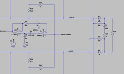
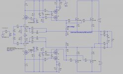
I have now post the system, I did also discover that it is also the case with dual supply on the driver that I have voltages on the two halves of circlotron, and as such, I get more then one volt out of rectifier with 512 mA idle current include the current plus voltages, so I do not now if that wil disturb things.
see the sim.
PS I have to say that ltspice 64 bit still do hang so now and then, I can not stop sim anymore and things standing still, lost every change.
regards
Attachments
Last edited:
Hi Kees!
I found something like this, I am not sure if it is EC or NSW circuit, maybe you will find it useful in your designs: http://forum.zelfbouwaudio.nl/downl...id=52bdb5d57235d5ea7f643bc47b2c42e3&mode=view forum: Circlotrom,pootje meer want anders - forum.zelfbouwaudio.nl
I found something like this, I am not sure if it is EC or NSW circuit, maybe you will find it useful in your designs: http://forum.zelfbouwaudio.nl/downl...id=52bdb5d57235d5ea7f643bc47b2c42e3&mode=view forum: Circlotrom,pootje meer want anders - forum.zelfbouwaudio.nl
Either one is not a circlo per say. However, assuming pretty good match of same channel FETs from the same batch you probably do not need differential or output zeroing but do need biasing. The latter is done by simultaneously changing either gate or source voltage in respect to ground. Surely enough input amplifier or discrete circuitry shall be referenced to the signal ground as well.
Either one is not a circlo per say. However, assuming pretty good match of same channel FETs from the same batch you probably do not need differential or output zeroing but do need biasing. The latter is done by simultaneously changing either gate or source voltage in respect to ground. Surely enough input amplifier or discrete circuitry shall be referenced to the signal ground as well.
That is quite right, I have zero on speaker because of canceling, but not on the resistors, changing the gate voltages for idle current do change the voltage also and can be seen on both speaker connectings, I can do it different, bet did get the same outcome, there is dc + your 180 mV current measurement.
Thanks for all the tips and help.
regards
Hi alex, very nice idea but I do not like voltage feedback, current feedback is much better for keeping bandwidth and much less TIM, much tube amps do use cathode feedback.
the problem is I gert a voltage on the output on both sides, not a problem for the offset afcourse, it cancels out.
What I can do, a small negative voltage on the jfet diff amp where feedback is so I can also cancel out the voltage, I do not use opamps, but you did I think done that for clarity.
I go look tonight, but first help friend who is operated in hospital and recover now.
A pity she is alcohol addict, I have not be managed to help here to stop that.
regards
Surely no point of drawing discrete amp. Secondly the thingy of yours is not exactly CFB, VAS for instance. Secondly you may inject bias into signal path, adjusting VAS operating point. DC coupling without monolithic (and not even LTP) is rather questionable, especially with JFETs not having straightforward zeroing sequence. Just FUI. Cheers
Last edited:
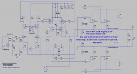
I have did change some, now I have low error on output, just 25 mV, by using two extra resistors and remove the two resistors from gate circlotron drivers.
This is because with these resistors I always need some volts to get them on, now it go through the extra supply and reference resistor, and it works now.
Maybe I need a dc servo, because it is current feedback, but a circlotron do cancel his offset out so matbe no need. but I go try this things, do now I did want a allfet circlotron.
Attachments
Last edited:
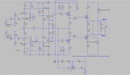
Here is a other version, I had more somewhere.
other has a current source below the Jfets, and a current feedback, however that did not work properly, get much distortions.
regards
other has a current source below the Jfets, and a current feedback, however that did not work properly, get much distortions.
regards
Attachments
- Home
- Amplifiers
- Solid State
- allFET circlotron