Jees, can't you, already having resistors at source, come up with the servo?
Thanks for response.
I do not now if that can be done, the output is floating and speaker between, if it can be done, I need sample and hold circuit who is between that output, with no speaker thing get really unstable.
I can try however a error correction like feedback servo with two bjt.
Later I go try and let now.
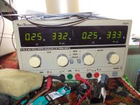
Pic is the present setup, it keeps in 250 mA for 6 hours now, heatsink is now 65 degree.,.
regards.
Attachments
Last edited:
Voltage at the source contains idle current by source resistor value while the one at the output does not. So, you need averaged difference of two precisely half-wave rectified voltages which basically yields the idle current of yours times source resistance. However in class A current through MOSFET never goes to zero you may skip rectification. The complicated part is rectification at higher frequencies, which would be pricey.
Ho Alexberg
Thanks for the advises, the autobias you do mention there is a lot of documantation about, special in the tubes area.
I have try with transistors as error correction who do work also, however what do happen with the sound, I have low pass the feedback from source resistors so it have no impact, but I did hear this kind of correction does compress the sound?, it does work very stable because did test this in the past, however abonded it because of the compression warnings. I did see distortion is higher with the bjt bias tracking but not so much.
Rectification for high frequenties can be done with skottch diodes, not so expensive, but the whole stuff is quite complicated, the circlotron needs te stay floating, a little disturbance do shoot distortion skyhigh. a normal amplifier with ground is a lot easyer to make a autobias, I be aware that a autobias give much lower distortions,, but we speak about 52 mV over the source resistors, that is little voltage and it need to be measured during the zero transitions, therefore a sample and holt is used in some designs.
But it is interesting to investigate,
regards kees
Attachments
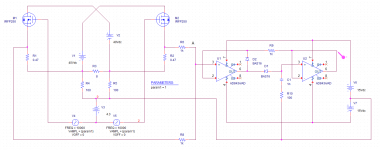
I have use now a opamp for better tracking, it even does set the offset very nice, do two things,.
I did read a lot about autotracking servos, much people have bad experiences with them in class ab, I have now try it in the circlotron, I do not now if i have done it the right way and or there is compression of music, however the servo do swing with the output stage so do see only dc voltages and because of floating amp, it does not compress I think.
It has also better distortions as with the bjt alone. but the need for a rail to rail opamp is really needed or it does not work wel.
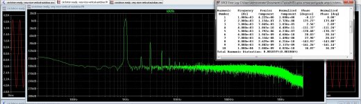
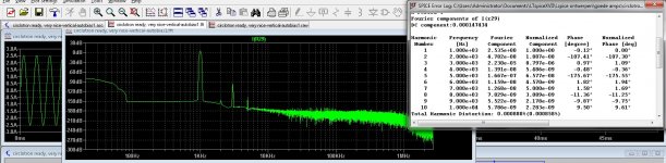
Last pic is a 25 Khz distortion measure.
regards
I did read a lot about autotracking servos, much people have bad experiences with them in class ab, I have now try it in the circlotron, I do not now if i have done it the right way and or there is compression of music, however the servo do swing with the output stage so do see only dc voltages and because of floating amp, it does not compress I think.
It has also better distortions as with the bjt alone. but the need for a rail to rail opamp is really needed or it does not work wel.
Last pic is a 25 Khz distortion measure.
regards
Attachments
Look, there is a reason for averaging only positive half-cycle to extract bias alone. Your solution measures the sum of output and bias current which is not what needed. For instance "standard" PP EF approach with opto takes into account the fact that average value of AC output current equals to zero. Thus exactly bias and only bias is controlled.
Cheers
P.S.@Kees52, I've have no intention to steer the design of yours from the route to completion. Approach mentioned was simulated and prototyped. Unfortunately it seems too complex.
Cheers
P.S.@Kees52, I've have no intention to steer the design of yours from the route to completion. Approach mentioned was simulated and prototyped. Unfortunately it seems too complex.
Look, there is a reason for averaging only positive half-cycle to extract bias alone. Your solution measures the sum of output and bias current which is not what needed. For instance "standard" PP EF approach with opto takes into account the fact that average value of AC output current equals to zero. Thus exactly bias and only bias is controlled.
Cheers
P.S.@Kees52, I've have no intention to steer the design of yours from the route to completion. Approach mentioned was simulated and prototyped. Unfortunately it seems too complex.
Ah you was the guy behind that complex opto coupler approach? I did read somewhere and see the schematic for that, but it was not for a cirlotron.
I have include the servo into the floating output, two separated servo,s that is, because the whole circuit is in the swing it do sees only the dc part, as that was what i did think. A circlotron are two single ended parts, driven with out of fase signals, the output is floating so the servo circuit needs also be floating the output 1Khz signals is not seen by the servo, it sees only dc.
It does work, but as I did read on much places, the idle current servo is special for class AB very difficult to implement. I think a sample and hold circuit and a little cpu can do better?. with single ended tubes, the idle control is very easy to do, it give a much better respons from tube also, better then with cathode bias.
Your help is welcome, your help is of value for me thanks.
In pic's the opamp input and output in ltspice is measured, and one pic I have measure the diodes over the source resistor, you see the dc component, that is only what the circuit sees because it is included in the floating supply of the circlotron output stage, all the signals are in fase of one half output, servo seeing only dc, same for other half, now we have a constant current output.
regards
.
Attachments
Last edited:
I have done some sims, but I see that I have just some millivolts to use for the servo, plus, the difficult part it has always needs to be above a minimum what the output signal will do, like max power, that is the difficulty and the complexing is about autopower.
However, I can cancel out the audio, so I have only a dc part, what I do camp with a diode and resistor, then I have 20 mV differences with 200 mA to 3 amp setup, that is little.
regards
However, I can cancel out the audio, so I have only a dc part, what I do camp with a diode and resistor, then I have 20 mV differences with 200 mA to 3 amp setup, that is little.
regards
This servo I did find on the internet as a example do work for some part, to get shure I need to build it.
The extraction of current from Rsource, where is also 7 volts dc do this not destroy measurement? the other part of the circlotron has also +7 volts. cancel offset to zero.
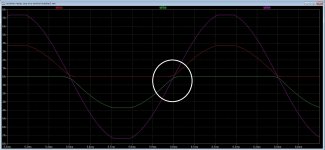
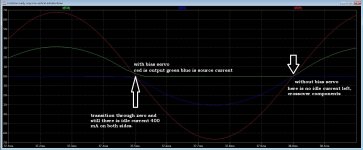
Here you can see with the servo I have done, only when I get clipping the idle current runs out of steam, I have still some 100 mA left see circle in pic.
for normal use and almost full power it seems to hold idle current stable.
regards
The extraction of current from Rsource, where is also 7 volts dc do this not destroy measurement? the other part of the circlotron has also +7 volts. cancel offset to zero.
Here you can see with the servo I have done, only when I get clipping the idle current runs out of steam, I have still some 100 mA left see circle in pic.
for normal use and almost full power it seems to hold idle current stable.
regards
Attachments
Hi Kees!
is the autobias you used making nonswitching operation for output mosfets?
I am not shure, but it looks like there is still bias, even when drive to almost clipping, when I do real clipping then it goes switching, but the theory about it, I am not that good on that part, but maybe people here can.
It was not mine attention to make a autobias, this because it is a circlotron and there is offset into the signal, 7 volts - 7volts = zero offset afcouse but for get the dc part for the autobias over the source resistors is then more difficult, so I have use two autobias now for each half, then it sees zero volts into the signal and can be used, if I am right afcouse.
But Alexberg seems to have much more experience with this.
regards
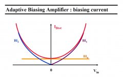
Bias
As soon as amp leaves A class, average current through fet departs from the initial value, see attach. Sorry the circuit of yours does average the current trough FET. Diodes in measuring circuit do not conduct due to absence of the reverse current through the fet.
As soon as amp leaves A class, average current through fet departs from the initial value, see attach. Sorry the circuit of yours does average the current trough FET. Diodes in measuring circuit do not conduct due to absence of the reverse current through the fet.
Attachments
As soon as amp leaves A class, average current through fet departs from the initial value, see attach. Sorry the circuit of yours does average the current trough FET. Diodes in measuring circuit do not conduct due to absence of the reverse current through the fet.
So maybe a circlotron can not be auto biased? because of the halves and floating output?, we need reference, it has with two resistors but maybe that put trouble, that is why I did put the opamp into the halves on each side.
This is a shortcoming of me, the theory, but calculating and such, I am hobbyist so, never get on school for learning theory, I do now much but the small difficult things, I can not, and an autobias is quite difficult as I have read on much places, where she do talk about using cpu for that.
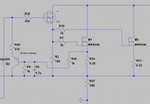
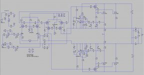
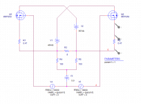
here is the schematic, just play some with it, it is better than see pictures.
regards
Attachments
Alex
I have sim with and without the auto bias, you are right, with the autobias I get even worse plots, the diodes are just pushed to the zero line, so I can not measure this way with a circlotron?. Nice afcourse to play, it is quite exciting stuff haha.
With the autobias you see clearly the crossover see last pic. so work to do and learn, need put the autobias outside the output stage. The opamp is grounded with the negative pin and also the rectifier diodes, so it can never go below that, problem occur. with a normal EF version we can use a negative voltage on the opamp also, here it can not.
You now I read a lot about autobias as mentioned, it is quite a challence I do read also and not much amps do use it. And class D get better and better.
regards
Attachments
As soon as amp leaves A class, average current through fet departs from the initial value, see attach. Sorry the circuit of yours does average the current trough FET. Diodes in measuring circuit do not conduct due to absence of the reverse current through the fet.
I think I have now get it, how do you use LTspice for the average sims? you let run it several times and with increasing amplitude until it levas class a the clipping part, you have it negative, but that is the same as positive afcouse, I have two halves what I need is the clipping do keeps away from zero, like 52 mV on each side, or am I wrong?.
one servo between the two halves? it cancels the audio signal, I go try that.
Look, it's not a LTSpice to begin with. I've already dismissed my own suggestion about auto biasing circlo due to complexity of the solution requiring half cycle measurement for instance.
Cheers
That is I think so little amps have that stuff because it is quite difficult to get idle on in the whole power range, if succeeded then you have a class A amp until full power with low idle, neat.
I did look at your plot, where I did see the signals stay below zero in the negative part, but I have the upper stage into the positive half of supply and the other is below that zero point, this amps needs diff signals to drive, maybe I look wrong, but it is clear, as with the output I did give you see clear that it is above and below zero point. when make the servo slow enough to filter out audio it works nicely as a bias servo but then it is class ab as normal still, it is better as a vbe multplier with temperature.
I agree with LTspice but it does be handy for the startup of a ideas, yes it needs to be build to check.
I can still use the opamp version I have, let it the normal class ab amp as with a VBE multiplier, this one is proberly much better and more stable, just make it low pass around 10 hz..
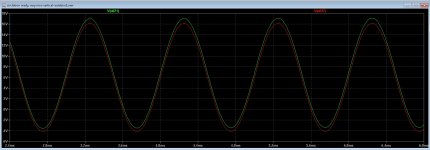
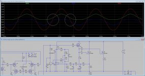
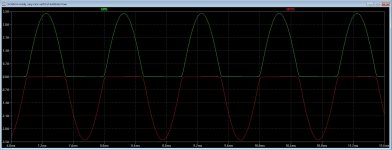
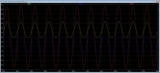
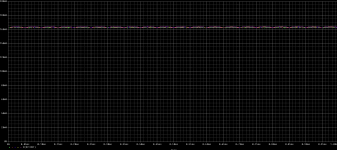
blue and green line is current over the source resistors and red is output signal, idle is 1 amps as test, the output is near clipping.
Attachments
Last edited:
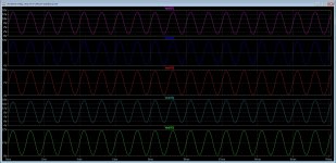
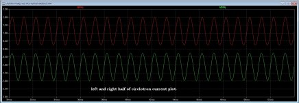
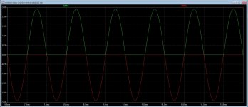
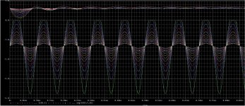
I have disable one half of the bias servo and drive amp fully, there is clearly some bias left on one half and nothing and class b on the other.
Do I drive to clip, both get in class B.
explane please, am I wrong here? diodes do conduct, have some Milliamps there. complicated stuff, therefore autobias the right way is difficult, but this do work quite nice as a normal bias tracker.
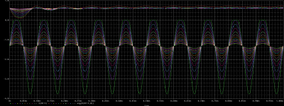
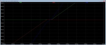
pic three is what we want, stable idle current on all output power.
Misschien ben ik eigenwijs, do not now the english word for it, maybe hardballs.
thanks.
Do I drive to clip, both get in class B.
explane please, am I wrong here? diodes do conduct, have some Milliamps there. complicated stuff, therefore autobias the right way is difficult, but this do work quite nice as a normal bias tracker.
pic three is what we want, stable idle current on all output power.
Misschien ben ik eigenwijs, do not now the english word for it, maybe hardballs.
thanks.
Attachments

- Home
- Amplifiers
- Solid State
- allFET circlotron