Interesting design. I tried the Sziklai scheme with high transconductance JFET. The sim gave good results, but not when built. The actual THD was not good. Could you please elaborate on your performance findings with the DMOS parts? My application needs low noise. I don't see much info for noise.I didn't really have trouble getting jfets, but got better results with the N-depletion MOSFETS (under condition of using only local feedback, which was more or less just an exercise)
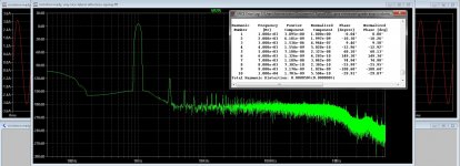
Performance on that circuit was pretty much as the sim predicted and very good (2nd HD some -72dB at 19V out, with 3rd and others progressively lower). But had to be in a cascode, otherwise distortion was much worse than predicted - the FET doesn't like its drain swinging much signal voltage.
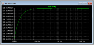
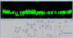
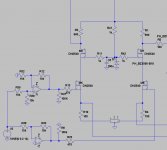
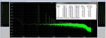
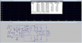
I never measured noise (don't have a good way to), but there is no audible noise when this 22dB amp is driving a 95dBSPL/2.83V/1m speaker with ear up close to the horn. The input impedance can be made very high if wanted. Here's the output of the noise sim per the settings shown in the schematic. I don't know how accurate it is, though.

R10 contributes about 100nV/rtHz of it, the input MOSFET about 18nV/rtHz. R27 contributes about 83nV/rtHz.
I never measured noise (don't have a good way to), but there is no audible noise when this 22dB amp is driving a 95dBSPL/2.83V/1m speaker with ear up close to the horn. The input impedance can be made very high if wanted. Here's the output of the noise sim per the settings shown in the schematic. I don't know how accurate it is, though.
R10 contributes about 100nV/rtHz of it, the input MOSFET about 18nV/rtHz. R27 contributes about 83nV/rtHz.
Attachments
Last edited:
I didn't really have trouble getting jfets, but got better results with the N-depletion MOSFETS (under condition of using only local feedback, which was more or less just an exercise)
I did see that you use also bjt there, and I need full mosfet.
I have replace the Jfet for 2N4393 and there a a lot of them on the internet I get very low distortion if I do set the jfet current on 4.8 mA.
Noise on a amp is not that difficult to avoid, I did not much care about it.
Attachments
Last edited:
Oh, well. Thanks for trying anyway, kees. I don't know why that doesn't work in your schematic. Are you using the same model for the FET as I attached? I think it was provided along with LTSPICE IV, so it probably is. I notice that the symbol used on yours looks different though than on my schematic (on mine is the same as the one used for your FET M1 (no body diode shown).
Thanks for the feedback Bwaslo. Can't beat practical info. JFET noise comes in at around 2nV/rtHz. I am building Sam Groener's low noise amp for just these type of measurements. I hope to find out what DMOS gives.
Kees, you say BF861 is noticeable better than the BF862. I tried BF862 and gave up on it. I am guessing you meant BF instead of BC. Sims for JFET do not seem to be reliable, so it is hit or miss when you build it.
Kees, you say BF861 is noticeable better than the BF862. I tried BF862 and gave up on it. I am guessing you meant BF instead of BC. Sims for JFET do not seem to be reliable, so it is hit or miss when you build it.
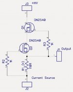
Have tryed with the dn2540, after change components because I did see the dn2540 hase very high transconductance so the source resistors and the current feedback resistors did need other value.
also I did need the drain resistors top cascode need smaller otherwise I get to much idle current, and 25 amps is a little to class A :hot
But it give only better HD with 1.5 amps output, when go to 3.5 amps it is almost the same as with the Jfets.
but it do work, however these are much more prone for gate defects if not properly protect.
I have use the BF861 because these did better idle setup transconductance is important I think getting a better current setup. I did also use the PN4383 who did also very good, for a normal line amp noise from these devices is not such a problem.
The idea that sims with jfet is not so precise, I do now that whole sim is not so precise, need adjustments, but it get close so I happy we can sim now these days.
regards
Attachments
Thanks for the feedback Bwaslo. Can't beat practical info. JFET noise comes in at around 2nV/rtHz. I am building Sam Groener's low noise amp for just these type of measurements. I hope to find out what DMOS gives.
Kees, you say BF861 is noticeable better than the BF862. I tried BF862 and gave up on it. I am guessing you meant BF instead of BC. Sims for JFET do not seem to be reliable, so it is hit or miss when you build it.
It is important the max current, and type C it is not bc but a bf, I did use the 862 but get a to low idle, some to do with trabsconductance?, 861 is higher and lower idle but did work better for setup the idle current in diff amp..
DB254 do work did change some resistors to get there.
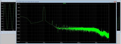
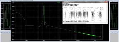
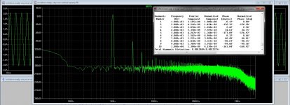
distortion on high power is much better and cleaner with the DN2540 mosfets. see pic 2.
Attachments
Last edited:
I use the DN2540 as CCS on the Aksa Lender Preamp too. Works great. The BSP129 is a nice depletion mode NMOS for SOT223 and that is used in Aksa Lender as well. Keantoken helped me to port the BSP129 model over from manufacturer’s Souce model to LTSpice.
AKSA's Lender Preamp with 40Vpp Output
But as a CCS, DN2540 is a great way to go.
AKSA's Lender Preamp with 40Vpp Output
But as a CCS, DN2540 is a great way to go.
I use the DN2540 as CCS on the Aksa Lender Preamp too. Works great. The BSP129 is a nice depletion mode NMOS for SOT223 and that is used in Aksa Lender as well. Keantoken helped me to port the BSP129 model over from manufacturer’s Souce model to LTSpice.
AKSA's Lender Preamp with 40Vpp Output
But as a CCS, DN2540 is a great way to go.
with this kind of ccs distorion is even lower because that is very high impedance, for tubes you get very liniair respons with low distortion what never can be done with bjt or mosfet.
regards
Attachments
I use the DN2540 as CCS on the Aksa Lender Preamp too. Works great. The BSP129 is a nice depletion mode NMOS for SOT223 and that is used in Aksa Lender as well. Keantoken helped me to port the BSP129 model over from manufacturer’s Souce model to LTSpice.
AKSA's Lender Preamp with 40Vpp Output
But as a CCS, DN2540 is a great way to go.
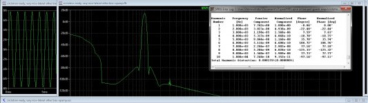
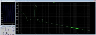
There is some difference this is a power amp, for that I have quite low distortion.
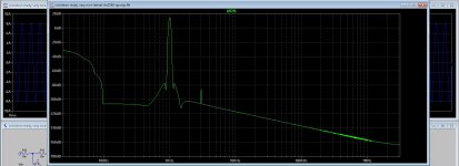
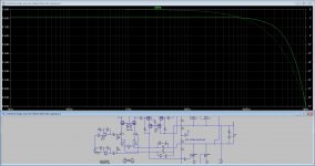
X how did you sim the frequency respons with LTspice?
but it do work, however these are much more prone for gate defects if not properly protect.:-
A back to back pair of BC546B b-c junctuons (act like very low C and very low leakage diodes) protects the gate well. Connect from gate to source, keeps the g-s voltage within safe limits. Other whise the gate oxide is easy to blow.
After change the jfet for a other 2n4393 type jfet things get even better, this fet do very well. these are also in other names like PN4393 the 91 and the 92 do not work well at all.
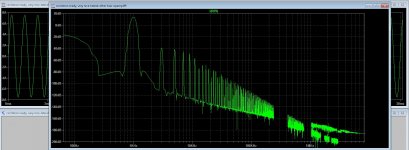
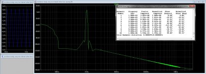
pic three is with high power, 8 amps out what is on the edge of the amp, some higher and it get high distortion.
this the lateral version, I put later one for the vertical version.
regards
pic three is with high power, 8 amps out what is on the edge of the amp, some higher and it get high distortion.
this the lateral version, I put later one for the vertical version.
regards
Attachments
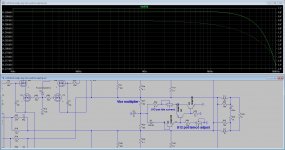
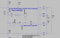
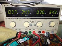
Ready now with the Vbe multiplier, it does work fine, I have temp compensated Q1 transistor who draw 50 ma and it did drift. Now it is stable when sandwiched to Q2, amplifier now stays withing 20mA from 25 to 80 degrees oC.
I did set idle high to get the heatsink hot for testing, normally it is 250 mA max.
Now it is time to get it on pcb.
I did set idle high to get the heatsink hot for testing, normally it is 250 mA max.
Now it is time to get it on pcb.
Attachments
Last edited:
Can't wait , please hurry
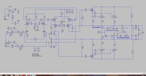
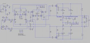
It is ready for pcb, and winter is coming, I do still think if I use a input transformer or opamps, for last I need extra supply.
The mosfets are full Cmos so amp stays allfet, the bjt vbe multiplier is outside audio path.
Attachments
- Home
- Amplifiers
- Solid State
- allFET circlotron