Hi All
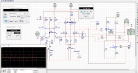
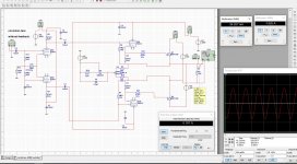
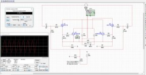
X ask me to post it here, so I do, some ideas behind it because I have simmed it only, but measures nice. distortion test in 4 and 8 ohm.
Maybe nice for a power J-fet .
regards
X ask me to post it here, so I do, some ideas behind it because I have simmed it only, but measures nice. distortion test in 4 and 8 ohm.
Maybe nice for a power J-fet .
regards
Attachments
Last edited:
hi X
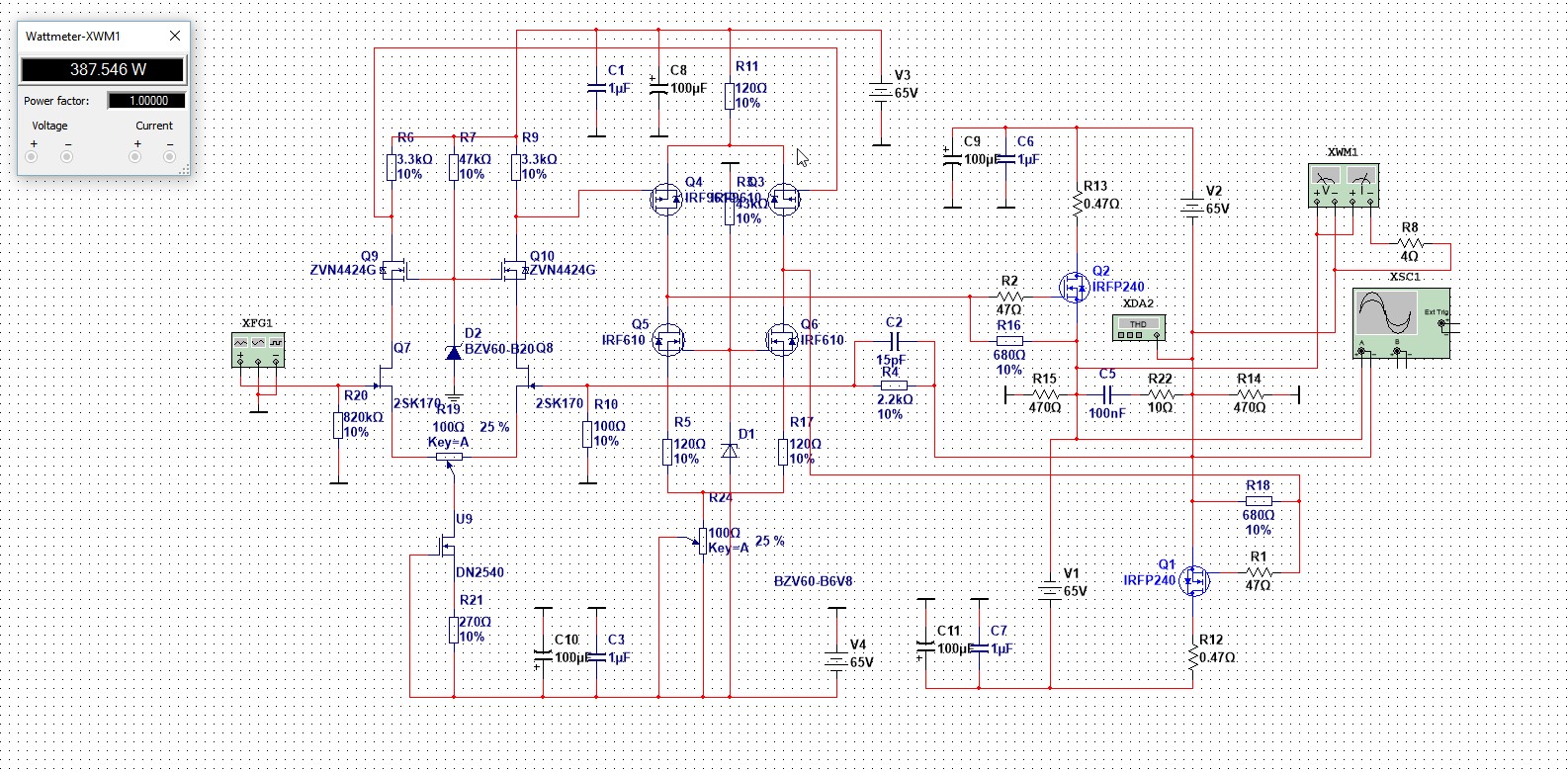
I have not yet build this, with two mosfets IRFP240 I think 100 watts is possible in 8 ohms, there are some things who has to be done, a temp sensitive resistor for the irp 240, I think idle go run away, with 2sk1058 however this is not the case (enhanced).
2 x 65 volts, normally the driver needs 8 volts extra for driving the mosfet output stage as it are source followers, but I think this is not so important with these aready high voltages,
The VA rating is for us diy people not difficult, 2x 65 volts 10/15 amps will do plenty it is just what you need.
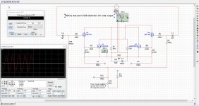
But the second schematic without a circlotron is just as good and more save to have no voltage on output as a circlotron has, as a quasy kind amp.
regards
I have not yet build this, with two mosfets IRFP240 I think 100 watts is possible in 8 ohms, there are some things who has to be done, a temp sensitive resistor for the irp 240, I think idle go run away, with 2sk1058 however this is not the case (enhanced).
2 x 65 volts, normally the driver needs 8 volts extra for driving the mosfet output stage as it are source followers, but I think this is not so important with these aready high voltages,
The VA rating is for us diy people not difficult, 2x 65 volts 10/15 amps will do plenty it is just what you need.
But the second schematic without a circlotron is just as good and more save to have no voltage on output as a circlotron has, as a quasy kind amp.
regards
Attachments
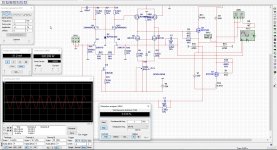
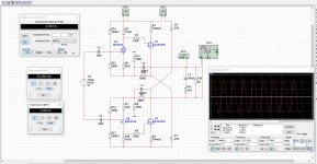
Is DC offset a problem? I ask that because there is no DC blocking capacitor is series with R10 feed back loop.
As with simulation there is not loop, it stays stable.
Have some changes in schematic, the pot on the j fets do setup offset who do nicely. I remove the other feedback loop, do not now precisely of this is really needed tie output together with two resistors give a wrong fase for the feedback and make it a oscillator, (a really good class d).
I do like current feedback more, because of better sound, I go look if it can be implemented with other schematic, do it over again.
regards
Attachments

Well, I think there are problems.
The bias current of the output stage is not stable.
By adjusting R24 the voltage for the gates of the output fet's are jumping from one end to the other.
The 680 ohm resistors probably limit the excursion but is that good ?(big drop in loopgain)
Also missing is an offset adjust.
Using just fet's is amusing but no very practical.
Mona
Last edited:
I think the Circlotron topology - offset is actually what drives the speaker as there is no "ground" on the load. It is floating ground so what offset are you referring to?
I think the goal is balanced outputs from the output stage drivers. Balancing them is balancing the IPS.
I think the goal is balanced outputs from the output stage drivers. Balancing them is balancing the IPS.
I think the Circlotron topology - offset is actually what drives the speaker as there is no "ground" on the load. It is floating ground so what offset are you referring to?
I think the goal is balanced outputs from the output stage drivers. Balancing them is balancing the IPS.
Hi X
If there is no ground, do not mean there is not a offset. and for the idle current, yes this can be a problem, special with the vertical mosfet, but maybe also the drivers, so need a correction, maybe a temp resistor of low omage on top of drivers.
Well, I think there are problems.
The bias current of the output stage is not stable.
By adjusting R24 the voltage for the gates of the output fet's are jumping from one end to the other.
The 680 ohm resistors probably limit the excursion but is that good ?(big drop in loopgain)
Also missing is an offset adjust.
Using just fet's is amusing but no very practical.
Mona
I think also you are quite right, what concerns my math knowledge it do short circuit.
But nice to play, what concerns the 680 ohm resistors, I have to look at if differently I go need to do a circlotron compound like amp, with extra drivers in the circlotron itselfs, the low ohms and a source follower do not work well, but when use a drain follower things change a little, here I need mucho less swing from the driver, but get trouwble with capasitance and miller
The offset I did with a pot between the j fets at input changing balans of them..
regards and thanks for thinking with us.
Hi X
I think something do not well, the sound quality because of the low ohms gate input, this can maybe compress things, however sim do let it work I do not now why this is so, I presume that sims are quite accurrate the last years.
Maybe draw it also in lt spice to see.
I let you here when I am ready.
regards
Hi Kees,
Typical gate drive resistor values in my other IRFP240/9240 projects have been using 220R and seems to work fine. Sims have been pretty good for me as long as model of transistor is decent. If you go with LTspice you can download Bob Cordell models. I have also heard Keantoken's models are very good too.
Typical gate drive resistor values in my other IRFP240/9240 projects have been using 220R and seems to work fine. Sims have been pretty good for me as long as model of transistor is decent. If you go with LTspice you can download Bob Cordell models. I have also heard Keantoken's models are very good too.

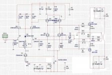
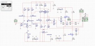
In an effort to change it to something that perhaps funtion I redraw the thing.Not that I would built it but it keeps me buzzy
Mona
Thanks to think with me, I have also done some research, and I do not get thing such why a circlotron with sound better, a quasy amp will also work, and is more easy, I do not like voltages are on the outputs when it toch a ground per mistake blowing things.
What is nice about a cirlotron is that the balanced idea make better sound, by using only N mosfets.
Did find some ideas, and go look at it.
BTW nice drawn schematic.
regards
I was searching on the net about circlotrons, it seems a very strange amplifier, because with floating loudspeakers but in my eyes it is not so strange, build a good one need balanced inputs so use a transformer is a idea is stead of a fase splitter of such.
I did find an old design I was busy with, and a circlotron also, but not a allfet but a hybrid amplifier because I like them.
seems that this looks very similar as TEM3200 has, not completely the same but driver and mosfets are, I did not copy it, just did came to it when try combine things
some years back.
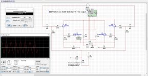
Did see it makes 100 khz blockwave very nice, low distortion with no feedback.
nice hehe.
regards
I did find an old design I was busy with, and a circlotron also, but not a allfet but a hybrid amplifier because I like them.
seems that this looks very similar as TEM3200 has, not completely the same but driver and mosfets are, I did not copy it, just did came to it when try combine things
some years back.
Did see it makes 100 khz blockwave very nice, low distortion with no feedback.
nice hehe.
regards
Attachments
Last edited:
In an effort to change it to something that perhaps funtion I redraw the thing.Not that I would built it but it keeps me buzzy
Mona
Hi Mona
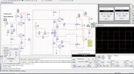
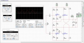
I have test the changes, you did replace the current source for J-fets input by a constant voltage, this because you want here do regulate the idle current? it do work, however the changes with the output power fet did not nicely work out, the 10 k resistors disturb the driver/splitter stage, so use the 680 ohms did work the best as I see in sim, a lot of distortions like so 400 % and a strange sinusoidal.
the idel current pot I have first on driver can maybe corrected by using a current source here and put fet on heatsink?, or use the 2sk1058 fets who do not have run away trouble.
When I do use lower ohm resistors it gets better, but the lowest distortion is 820 ohms, between gate and source as was, the output of the driver do best that way. The pot like you did mention do work for idle current bu is very sensitive.
thanks .
kees
Last edited:
I think you can put a Vbe multiplier to control the temp runaway. An IRF540 is convenient since it has a bolt hole to clamp to same heatsink. It's larger mass than a BD139 (which I have used as temperature feedback Vbe). But here is an AllFET so no BJT's need apply.
Hi X
A vbe multiplier is maybe some more difficult, I do now when use a allfet amp I need a fet for this, as the irfp is a hexfet maybe use another hexfet will do, just to get a negative action on a positive action, hihi, nice said.
regards
I have made two circlotron output stages, one is a compound like setup and a other are source followers. be made this first I get some hang on it and can later on do the drivers stages and fase shifter.
But for now first the horn testing work or I get to much to quick.
regards
But for now first the horn testing work or I get to much to quick.
regards
Attachments
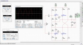
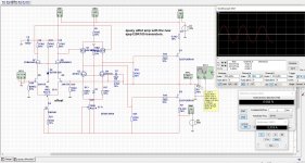
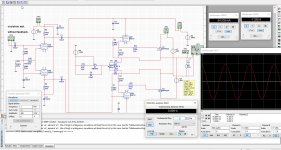
Here another one who do well, now I have connect the drivers in opposite against power fets as seen on a patent to fight distortion and cancel out dc drift.
looks good, it amplifies 2 times, source followers making lower impedance, go to 500 Khz with ease, as shown with sim, not shure in real, can be used with power power J-fets ?.....
looks good, it amplifies 2 times, source followers making lower impedance, go to 500 Khz with ease, as shown with sim, not shure in real, can be used with power power J-fets ?.....
Attachments
- Home
- Amplifiers
- Solid State
- allFET circlotron