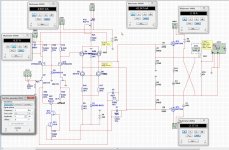
New correcting zip and schematic simulation for upset of amp, so you have a start.
Keep me informed.
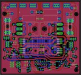
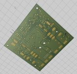
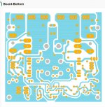
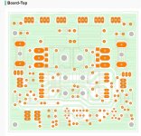
The last picture is most current one, and also the zip file included.
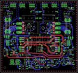
The board has no errors, that is what I like about pcb software who help me prevent that, I have do a urp from a pcb house for extensive check, and I do not see airwires anymore what mean everything is connected.
but it is oke to test it afcourse, I have put everything in the zip file, including pcb design, so it can be tested.
regards
Keep me informed.
The last picture is most current one, and also the zip file included.
The board has no errors, that is what I like about pcb software who help me prevent that, I have do a urp from a pcb house for extensive check, and I do not see airwires anymore what mean everything is connected.
but it is oke to test it afcourse, I have put everything in the zip file, including pcb design, so it can be tested.
regards
Attachments
Last edited:
If you do drc in eagle and have miss a small trace it do not give a error, just a airwire, with diptrace it say alarmm alarmm haha.
this is a minus also, I need a audible or tekst window saying one trace is not connected. I see a airwire show up, but if it is a small disconnected wire you do not see it.
regards
thats the reason why I said you should do a ratnest, on the left hand corner you will see number of airwires still remaining. then you switch on only dimension and unrouted layers and see where the airwires are, no matter how small. use a bright color for "unrouted" layer so that you can see!
But....
If you dont know how to use eagle or cant 'see' air wires, you should use diptrace, all the best!
reg
Prasi
Should we be using J310 or 2J113 for Q3 and Q4?
J310:
http://danssmallpartsandkits.net/J309-D.pdf
2SJ113 seems to come in TO92 and big TO3P packages. Obviously we want TO92.
thats the reason why I said you should do a ratnest, on the left hand corner you will see number of airwires still remaining. then you switch on only dimension and unrouted layers and see where the airwires are, no matter how small. use a bright color for "unrouted" layer so that you can see!
But....
If you dont know how to use eagle or cant 'see' air wires, you should use diptrace, all the best!
reg
Prasi
Hi Prasi
I do see airwires, that is not the problem, however most software do use better error generation, all pro software do giving a message, with eagle I do need to be a type goeroe but I was already started, the next time I go to diptrace or ultiboard in multisim. I do not make pcb,s every day, so I do not now everything about eagle, but did find that more people do not like the way it works, me included. Why eagle do not highlight a not connected wire like ultiboard does or other software?.
I have zoom the pcb to search for airwires but all is connected. see what happens when not in picture but eagle do not give message about it. I agree that eagle has a very nice graphic outlook, very professional looking.
X the jfets are J113, but it is a current source cascoded so we have high impedance for using unbalanced input with one earthed. other j-fet can be used when adjust the resistor and it has enough current capability, but J113 do wel.
regards
Attachments
Last edited:
Should we be using J310 or 2J113 for Q3 and Q4?
J310:
http://danssmallpartsandkits.net/J309-D.pdf
2SJ113 seems to come in TO92 and big TO3P packages. Obviously we want TO92.
It is a typo X use a J110, but j113 is also in to92 housing that can be also used and is the one
to use, not the power version I did saw..
I go check the board a last time to see with Prasi tips to find possible errors.
in the zip file however are also the design files, so you can import then right away in eagle.
regards
Last edited:
thats the reason why I said you should do a ratnest, on the left hand corner you will see number of airwires still remaining. then you switch on only dimension and unrouted layers and see where the airwires are, no matter how small. use a bright color for "unrouted" layer so that you can see!
But....
If you dont know how to use eagle or cant 'see' air wires, you should use diptrace, all the best!
reg
Prasi
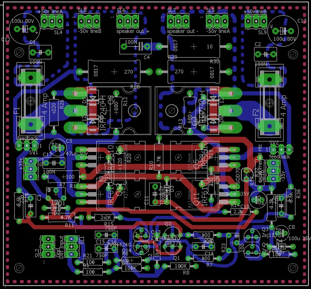
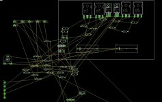
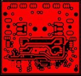
As far as I see this is a ratsnest? so did thing the right way my friend.
Attachments
X and Prasi
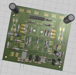
I have now follow your advise and test the board for open connections, did need to studie it to find out how, but i do know now, still so much work to set things up in eagle in compare to others, but worth it.
X the bom, (carefull we are allergic to Bom here) is also present in zip.
I did find errors, but only a wrong shape for the j113.
Now all is oke, did not find trouble.
regards
kees
Attachments
Last edited:
Hi Kees,
Sorry to bother you about this...
I tried uploading the Gerber zip file to Seeedstudio Fusion and I get the following error messages:
It seems the format you have is not standard. The above files seem to be in the zip archive you provided but the fab house has trouble reading it. Does anyone else have better luck? All the Gerbers that Prasi or Sonal have provided thus far have worked without errors.
I will try uploading to PCBway and see if they give me errors too. They have a human review the file so takes time.
Thanks,
X
Sorry to bother you about this...
I tried uploading the Gerber zip file to Seeedstudio Fusion and I get the following error messages:
File comp.ps was not identified.
File silk.ps was not identified.
File solder.ps was not identified.
Project does not specify any drill hits
It seems the format you have is not standard. The above files seem to be in the zip archive you provided but the fab house has trouble reading it. Does anyone else have better luck? All the Gerbers that Prasi or Sonal have provided thus far have worked without errors.
I will try uploading to PCBway and see if they give me errors too. They have a human review the file so takes time.
Thanks,
X
Kees,
I have IRF510 already in hand. Can they be used rather than the 610's? They are 100v Vds but 4amps. Do we need 200v Vds for the driver stage?
I have to order the 2SJ113's though and also the ZVN4424's - is the "A" type OK or do I need the "G" type?
I pretty much have everything else already so good to go BOM wise I think.
Kees,
I have IRF510 already in hand. Can they be used rather than the 610's? They are 100v Vds but 4amps. Do we need 200v Vds for the driver stage?
I have to order the 2SJ113's though and also the ZVN4424's - is the "A" type OK or do I need the "G" type?
I pretty much have everything else already so good to go BOM wise I think.
Hi X
the mosfets are choosen because of low capacitances and she look to each other in specs irf710 for example do better.
You can try it, but the on voltage will be different and the capacitance higher, mosfets with higher voltages is not choosen by accident but because she are availabl
The output of the board is from a ulp file, who is given to me by a pcb manufacturer. If you tell mee what manufacturer you choose I go ask for you for a ulp.
I have viewplot and these do load them without problems.
I have also need to order the J113, these are nice current sources and available, I have seen and heard that the J109 is oke for audio and available..
regards
Attachments
X and Prasi
I have now follow your advise and test the board for open connections, did need to studie it to find out how, but i do know now, still so much work to set things up in eagle in compare to others, but worth it.
X the bom, (carefull we are allergic to Bom here) is also present in zip.
I did find errors, but only a wrong shape for the j113.
Now all is oke, did not find trouble.
regards
kees
ok kees,
just trying to suggest thing or two i learnt for ease of design validation of your design. it may be better to use white background and bright red unrouted layer color for checking of remaining airwires is all i was saying. once you press ratnest, on the lower left corner briefly you will see number of airwires remaining. if it says briefly "nothing to do", you are good to generate gerbers
") . use gerb274x.cam (available in default location) for making gerbers and carefully select only the layers you want active on each of the gerber section (e.g. plc, cmp, etc), for drills you can use excellon and generate a .drd file which will be acceptable to almost all boardhouses.
. use gerb274x.cam (available in default location) for making gerbers and carefully select only the layers you want active on each of the gerber section (e.g. plc, cmp, etc), for drills you can use excellon and generate a .drd file which will be acceptable to almost all boardhouses.reg
Prasi
ok kees,
just trying to suggest thing or two i learnt for ease of design validation of your design. it may be better to use white background and bright red unrouted layer color for checking of remaining airwires is all i was saying. once you press ratnest, on the lower left corner briefly you will see number of airwires remaining. if it says briefly "nothing to do", you are good to generate gerbers
reg
Prasi
Thanks Prasi
I have check and see nothing to do, when delete one trace it says one left, so yes now I can see what I do thanks.
For output cam, most of the pcb manufacturers do give scrips for that so always things are oke.
the last I did download was gerber 274X because these are most used.
X You can use the irf 510 because it is part of the current mirror, so it will work because the S and D capacitance is in series with upper irf 9610, the fact she are high voltages is just she are that way but looks close to each other and such, for the zvp4424 G or A not mathers you can use the old bss serie phillips mosfets who are 100 volts, do work because voltage over them is 42 volts in design, I can maybe also use them because she are cheap, but old..
regards
Hi X
The problem is not here present, the output is read properly.
exept the bom file who is not but that is normal, all the rest is oke, even the drills.
regards
The problem is not here present, the output is read properly.
exept the bom file who is not but that is normal, all the rest is oke, even the drills.
regards
Attachments
Last edited:
Thanks for checking. I wonder what's the issue with this one manufacturer?
Edit: I got a reply from the second PCB house and they also report a problem:
"Sorry but here a problem with your Gerber files : there is no Drill file (.txt/.drl) / solder mask layer
please check it and re-uploading the correct Gerber files on our site for check again."
This is PCBWay - so there is maybe a missing drill file?
If you can, please generate another set of Gerber files following the advice of Prasi?
Thanks,
X
use gerb274x.cam (available in default location) for making gerbers and carefully select only the layers you want active on each of the gerber section (e.g. plc, cmp, etc), for drills you can use excellon and generate a .drd file which will be acceptable to almost all boardhouses.
reg
Last edited:
Hi X
I do follow Prasi advise put a drl in for you with eagle standart excellon, then it will work, the .txt can then be removed.
Whait for me because I have found a airwire I can not find, eagle complains about it, that is what I do not like about eagle
error generation is problem, software act as in Linux, type software.
today I do send the proper files.
regards
Last edited:
- Home
- Amplifiers
- Solid State
- allFET circlotron