Hi,
Been lurking this forum for many years, its a great resource. This is my first post though. I was hoping you could help me figure out what I am missing trying to fix my Yamaha RX-V3800:
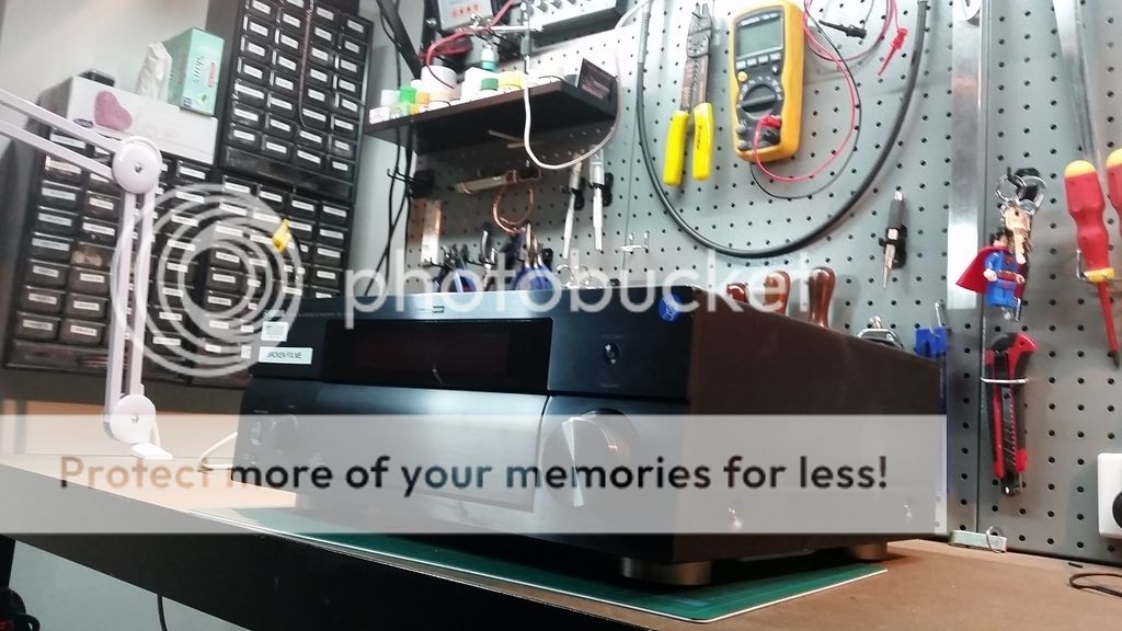
I picked the amp up for a song from a film studio, who were selling off about 10 of them at once (I would have bought more if I had the room to store them). The problem listed was that the amp was not powering on – I was hoping that a power supply capacitor was blown, which is a very common problem for these RX series Yamaha amps. I’ve got another one that had exactly this problem.
Unfortunately, this is not the case, instead the amp powers on, and then shuts off after three seconds. I managed to get my hands on the service manual, which tell me that this is the protection circuitry cutting in, shutting off the amp.
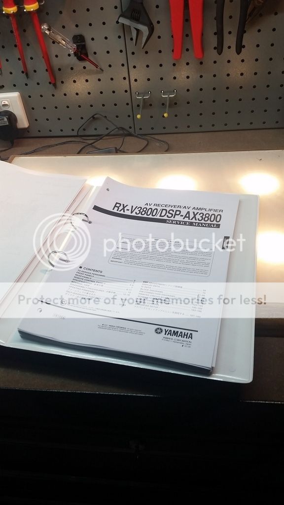
Fortunately you can override the protection circuity by pressing a series of keys on the front panel together:
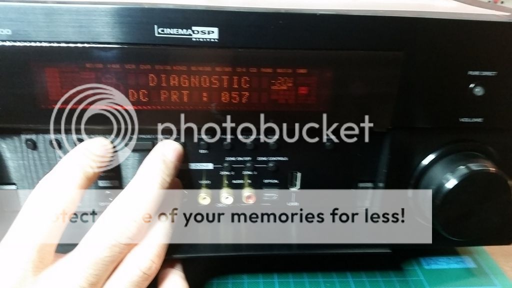
This brings up a diagnostic test, and also allows you to power on the amp (protection circuitry disabled obviously). The fault displayed is : Diagnostic DC PRT : 057. Consulting the service manual tells me that this indicates a DC voltage across the output.....
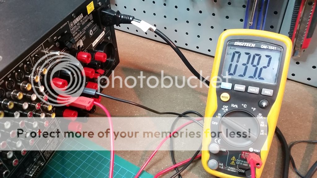
Bingo! 39V across the Right Rear Surround channel. All the other channels seem fine and have around 10mv of DC offset. My first thought was blown output transistors slamming the output into one of the power rails. I spent the next few hours pulling the amp apart to get to the main amp board (of course you have to pull literally every other board out to get to it):
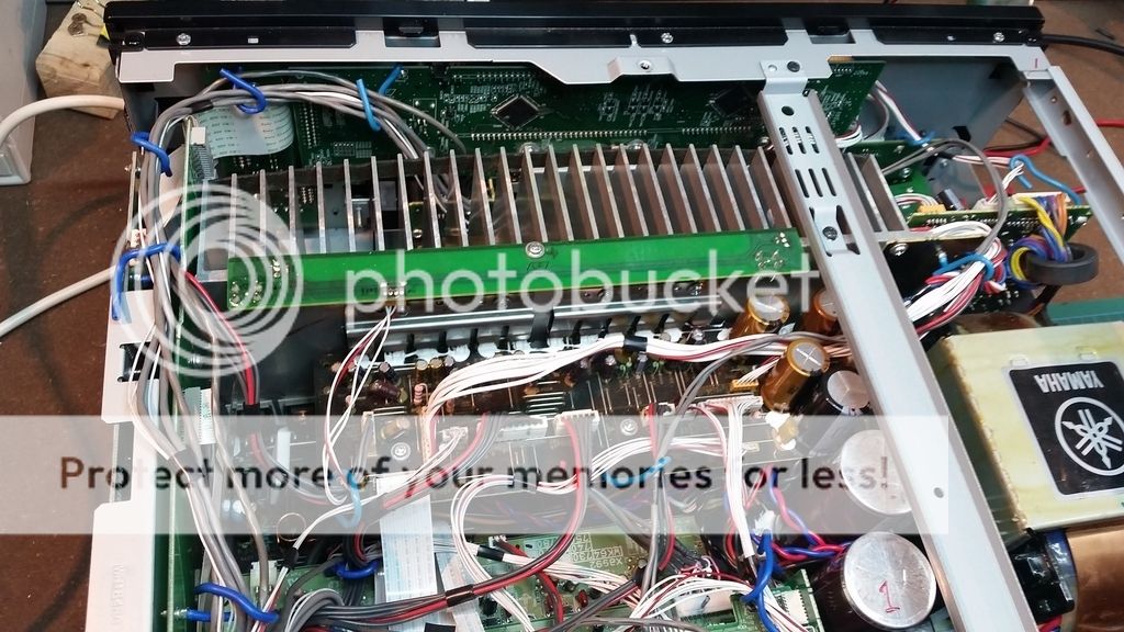
Here my problem; all the output transistors seem fine. No short circuits, and responded appropriately in diode test mode. I even found the schematics for the channels and started checking all the ICs in the circuit:
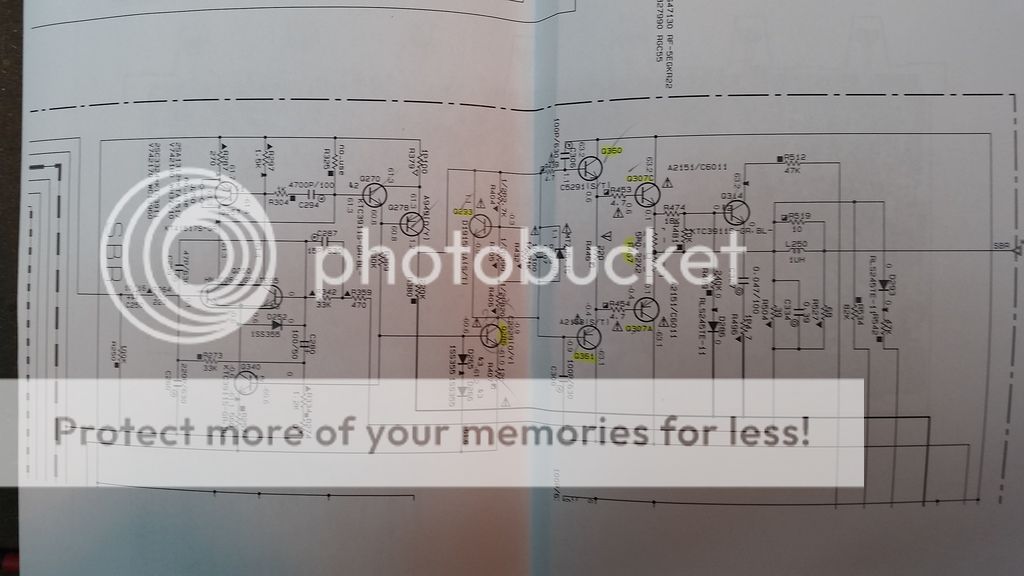
All the ICs Ive ticked above are good; I was going to start testing all the passives, and even start desoldering and testing out of circuit, but thought I would check here first, in case I am missing something obvious.
The other thing that is causing confusion is that i checked the primary supply rails, and they are 60v +- rails, not 39V. My understanding is that a shorted output transistor would leave a 60v DC offset on the speaker terminals, not 39V.
So my question is, what am I missing? Is there something obvious that would put a 2/3 of the rail voltage on the speaker outputs, without damaging the output transistors (as far as I can tell)?
Thanks for any suggestions!!!
Yes they are a little compact to say the least and it is always the rear or surround channels that fail as the users play a non Dolby Surround source, wind up the power and then put a Surround source on and overload the amplifiers.
I had a complete set of extension boards for Yamaha amplifiers but when I retired, I returned them to Yamaha as they were only on loan. Good luck but stay with an open mind. It will be either a semiconductor in the output stage or a safety resistor blown and giving no drive.
I had a complete set of extension boards for Yamaha amplifiers but when I retired, I returned them to Yamaha as they were only on loan. Good luck but stay with an open mind. It will be either a semiconductor in the output stage or a safety resistor blown and giving no drive.
Have you done a smell test to check for an obviously cooked part? Also close visual inspection with a bright flashlight may reveal a brown or charred heat damaged part. My guess is that it is a bad driver transistor. A little TO-39 feeding the misbehaving output transistor. What about the 5.1v Zener?
As a last resort - if you can live without one surround channel, just remove the output transistors and see if the problem remains and the amp otherwise works. This lets you probe the voltages going to the transistor too.
As a last resort - if you can live without one surround channel, just remove the output transistors and see if the problem remains and the amp otherwise works. This lets you probe the voltages going to the transistor too.
Last edited:
Thanks xrk971,
Yeah first think I did was the smell test and visual inspection. Ive got one of those gooseneck magnifying lights so was able to get a pretty good look - ill have a another run at it though to make sure.
Thanks - i checked the driver transistors, as I thought the same thing, they seemed ok, certainly non were shorted - Ill check again though to make double sure. I didn't even think to check the zener though - will definitely take a close look at that.
Good idea on the last resort - if worst comes to worst, i might just do that.
Thanks!
I'm not an A/V expert, but one quick peek at the back panel fills me with visceral dread at the thought of trying to work on that monster. "Doesn't power on" means it probably isn't a minor repair. Just getting the thing apart enough to work on must be a considerable challenge. Maybe PM wpas and see how her/his effort turned out. He/she and JonSnell Electronic both have first-hand experience with that piece, I do not.
Try low-balling 'em -- it might be worth a pittance but surely not 100 Euro. Its a door-stopper as it is -- they're probably just hoping beyond hope to get anything out of it. (Dunno what it cost originally, but it must have been substantial.)
Cheers
Rick
Try low-balling 'em -- it might be worth a pittance but surely not 100 Euro. Its a door-stopper as it is -- they're probably just hoping beyond hope to get anything out of it. (Dunno what it cost originally, but it must have been substantial.)
Cheers
Rick
Last edited:
Hi all,
Sorry for the slow reply on this. I did actually manage to get her working again - ran my soldering iron over all the solder joints for the driver and power transistors. After this she worked just fine and has been going strong ever since.
Must have been a cold solder joint causing an intermittent fault. I got lucky as none of the components actually had any issues.
Definitely well worth the effort given i picked the unit up for only $50.
Good luck to those trying to fix their own!
@ wpas
That's good information. I have two RX-V1900 here, one with similar strange issues as yours, and one that I got as spare parts from trean27 in Norway.
That one have a psu-board that won't work.
My RX-V3010 had to go Yamaha service last year.
I didn't manage to get a clue what was wrong with it, other than that it went in protection. IIRC They switched out Digital 1 board, cost ~135 Eur. Not that bad.
I'm not surprised that there are problems with those AVR's, not only Yamaha. They run hot, and with rather complex cirquits, in a tight box with maybe 15 diffrent PCB's mounted in all directions. To complicated ?
/Figge
Hi all,
Sorry for the slow reply on this. I did actually manage to get her working again - ran my soldering iron over all the solder joints for the driver and power transistors. After this she worked just fine and has been going strong ever since.
Must have been a cold solder joint causing an intermittent fault. I got lucky as none of the components actually had any issues.
Definitely well worth the effort given i picked the unit up for only $50.
Good luck to those trying to fix their own!
Not 100% sure it applies here, but I've seen cases where thermal stress inside some of the tightly packed units is causing the lead free solder to break connections. It is apparently quite brittle.
no power RX-V Yamaha
Hi
For the guys that use an older type RX-V Yamaha Receiver, when it does not power on, very often the small Capacitor on the powersupply board is broken, the value way lower than the specified 22 nF, replace it with a high quality cap, it is, on most boards the C4 cap.
Cheers, Tom.
Hi
For the guys that use an older type RX-V Yamaha Receiver, when it does not power on, very often the small Capacitor on the powersupply board is broken, the value way lower than the specified 22 nF, replace it with a high quality cap, it is, on most boards the C4 cap.
Cheers, Tom.
Same problem
Hi WPAS, found this old thread and hoped it would help me as well: I've a RX-V800 with exactly the same problems: DC (36V) on rear right out, identical message in the DIAG menu, initial suspicion that drivers would be defective so changed all active components (transistors, diodes) as well as all capacities in the rear right stage >> still not working, then found this thread and ran also over all soldering joints but still the same issue.... can you explain what joints exactly you resoldered? I took all starting from power input to last driver stage but maybe there's a specific joint I missed? I can't see any bad soldering visually.... looking forward to your reply. Cheers, Rob
Hi WPAS, found this old thread and hoped it would help me as well: I've a RX-V800 with exactly the same problems: DC (36V) on rear right out, identical message in the DIAG menu, initial suspicion that drivers would be defective so changed all active components (transistors, diodes) as well as all capacities in the rear right stage >> still not working, then found this thread and ran also over all soldering joints but still the same issue.... can you explain what joints exactly you resoldered? I took all starting from power input to last driver stage but maybe there's a specific joint I missed? I can't see any bad soldering visually.... looking forward to your reply. Cheers, Rob
One step further
Did futher examination and it turned out NOT to be the driver stage:through connection CB01 - CB231 the stage is steered through a.o. Q244 - Q245, when I disconnect CB231 the voltages in the rear right driver stage are ok, so the problem is somewhere on the video board.... looking further into this...
Did futher examination and it turned out NOT to be the driver stage:through connection CB01 - CB231 the stage is steered through a.o. Q244 - Q245, when I disconnect CB231 the voltages in the rear right driver stage are ok, so the problem is somewhere on the video board.... looking further into this...
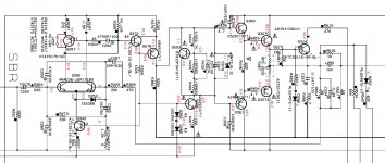
Out of curiosity looked up the RX-v3800 amp schematics, as OP attached pictures from external link, which isn't recommended due to link rot phenomenon, I will attach just the power amp stage shematics here for a quick access for anyone it may interest.
The whole manual is available here:
YAMAHA RX-V3800 AX-V3800 SM Service Manual download, schematics, eeprom, repair info for electronics experts
https://www.vintageshifi.com/repertoire-pdf/pdf/telecharge.php?pdf=Yamaha-RXV-3800-Schematic.pdf
Yamaha RX-V3800 Audio Video Receiver Manual | HiFi Engine
The whole manual is available here:
YAMAHA RX-V3800 AX-V3800 SM Service Manual download, schematics, eeprom, repair info for electronics experts
https://www.vintageshifi.com/repertoire-pdf/pdf/telecharge.php?pdf=Yamaha-RXV-3800-Schematic.pdf
Yamaha RX-V3800 Audio Video Receiver Manual | HiFi Engine
Attachments
Last edited:
- Home
- Amplifiers
- Solid State
- Yamaha RX-V3800 - What am I missing?