For the interest of DIY I have decided to create a build thread of a big 6 channel amp I am in the process of building. Some of you may have already seen some of the design from the grounding thread over the past few weeks. I will be posting some build photos as I go along. Enjoy!
The special "feature" about this amp is the budget. So far spending is not more than £140 with almost all parts acquired thanks to friends in the industry, good luck and a keen eye. Obviously this means a degree of compromise but so far this hasn't proved to be much of an issue.
The special "feature" about this amp is the budget. So far spending is not more than £140 with almost all parts acquired thanks to friends in the industry, good luck and a keen eye. Obviously this means a degree of compromise but so far this hasn't proved to be much of an issue.
Last edited:
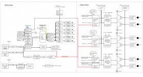
First attachment showing over all architecture. Fundamental functions are as follows:
I don't think I'm going to bother with bridging or Lightspeed attenuator as it doesn't seem necessary, may implement in the future if required. I've chosen not to put anything fancy like a micro controller in as I like the simplicity of it being a big dumb powerful amp with exactly all the control I want.
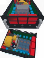
Second attachment showing CAD drawing in Tinkercad. I highly recommend this website for quick modelling although there are constraints. The greatest being when it came to marking up panels to drill the script won't give you centre's from an origin of any object. The drawing is a bit out of date now but most of the stuff is there.
- 6 x 250W output into 8 ohms with near enough perfect doubling of power into 4 ohms
- Independent high quality power supply comprising of 53400uF per channel derived from one large 5kVA transformer.
- Master and slave switched IEC inlet IF more power is ever needed when used as a PA amp etc
- SSR Relays for output and protection switching.
- Power saving Thryristor bridges completely shutting down channels independently, based on a timeout.
- Remote and pass through switching to be used as part of a rack.
- Super regulator circuits for all preamp circuits.
- PPM and clip monitoring for each channel.
I don't think I'm going to bother with bridging or Lightspeed attenuator as it doesn't seem necessary, may implement in the future if required. I've chosen not to put anything fancy like a micro controller in as I like the simplicity of it being a big dumb powerful amp with exactly all the control I want.
Second attachment showing CAD drawing in Tinkercad. I highly recommend this website for quick modelling although there are constraints. The greatest being when it came to marking up panels to drill the script won't give you centre's from an origin of any object. The drawing is a bit out of date now but most of the stuff is there.
Attachments
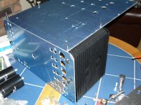
First attachment depicting chassis propped together, nothing drilled at this point except the front panel.
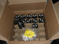
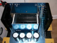
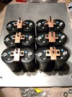
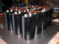
Second attachment depicting chassis mounted tank caps.
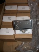
Third attachment depicting PPM meters,
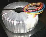
Forth attachment depicting Power transformer.
Second attachment depicting chassis mounted tank caps.
Third attachment depicting PPM meters,
Forth attachment depicting Power transformer.
Attachments
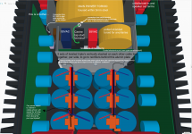
Yes the heat sinks certainly won't do full power all channels driven from convection alone. I have two 240mm fans I will place on each side if I really need it for some reason. They should just about manage 1500W in a well ventilated area though on programme material, they are 5.25U x 520mm.
I am designing each channel to be capable of the power output even though it will not be possible to obtain this power simultaneously. I haven't fully decided on what amps I will be using yet.
I am designing each channel to be capable of the power output even though it will not be possible to obtain this power simultaneously. I haven't fully decided on what amps I will be using yet.
I've come up with a solution to the high voltage transformer, I have a 600VA 30-40V transformer lying around I will box up separately and make it a plug in module where the output voltage is out of phase with the mains. This will reduce the secondary of the master 5kVA transformer to more usable voltages and give me the benefit of having two power modes for different impedances.
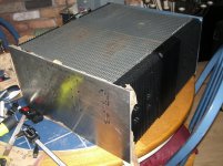
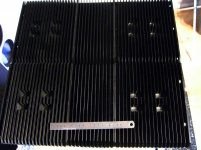
For those interested from the heat sink thread, heatsinks attached.
I have intentionally taken them with flash off as it made the look god awful as anything metal does. This image is an accurate reflection, they are basically perfect now")
For those interested from the heat sink thread, heatsinks attached.
I have intentionally taken them with flash off as it made the look god awful as anything metal does. This image is an accurate reflection, they are basically perfect now
Attachments
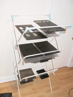
Some more build photos for those interested.
Heatsink thermal plate design.
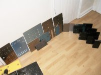
All pieces used for the project! (definite over design)
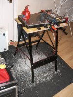
Testing panel fittings with heatsinks
Internal fittings
Front and rear plate spraying
Plate drying
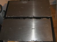
Rear of heatsinks before final polish.
Heatsink thermal plate design.
All pieces used for the project! (definite over design)
Testing panel fittings with heatsinks
Internal fittings
Front and rear plate spraying
Plate drying
Rear of heatsinks before final polish.
Attachments

Last edited:
- Status
- This old topic is closed. If you want to reopen this topic, contact a moderator using the "Report Post" button.
- Home
- Amplifiers
- Solid State
- monster-6-channel-amplifier-build-thread