Hello everybody,
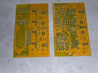
my bunch of PCBs arrived from PCBWay, and i am strarting now to build up the amplifiers. Thanks again for that wonderful design to Suzy Jackson.
So, what are the hints and tricks to make this beautiful amps successfully work.All parts (Melfs, capacitors, SMD transistors, driver and powe transistors are already available. The pcbs are double layers with 2 oz (70µ) copper. As far as i know, Suzy uses 3 oz PCBs.
Any comments to that project???
Best regards
Gunni
Buna seara Alexandru,
nice to get with you in contact here. i read a lot about your designs and brilliant work here. It's a real pleasure to get with you in contact.
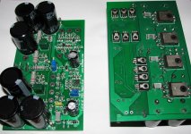
As i saw on the picture, you built already this amplifier. What's your experience with that nice amp.How do you estimate the quality of that design. Are there any tricks (Parts, type of parts. changes in equipment) to get the maximum quality out of that design.
My plan is a dual mono design with about 2x40 AC toroid transformers.
Multumim si la revedere
Günther
nice to get with you in contact here. i read a lot about your designs and brilliant work here. It's a real pleasure to get with you in contact.
As i saw on the picture, you built already this amplifier. What's your experience with that nice amp.How do you estimate the quality of that design. Are there any tricks (Parts, type of parts. changes in equipment) to get the maximum quality out of that design.
My plan is a dual mono design with about 2x40 AC toroid transformers.
Multumim si la revedere
Günther
Hi Gunther ,
What can I say , thanks for those kind words addressed to me , and about the boards ,they are with dust right now . They was never functional (lake of time ) ,maybe in the future. I think they will perform nice ,without any problems .
You must pay attention to rectifier bridge to be selected correctly ,something like 36A and voltage over 100V or so and heat sink for drivers and final transistors.
I wish you success .
Regards ,Alex
Hi fannatic,And what about the input transistor? Anybody knows a substitute for this transistor, reading the datasheet this transistor was discontinued. Any store dont have this transistor in stock, and i really would like to make one of this fantastic amplifier. Please help me!
sorry for the late answer. If you talk about the Fet input transistors, i can send you a positve reply, They are still available as SST404 from Calogic.
https://www.google.de/url?sa=t&rct=..._A.pdf&usg=AFQjCNFO1U0wGCMwc4U2IK4VY4QZx7rWDA.
i got them here in Germany for about €8 per piece.
Best regards
Günni
Sorry for the late answer to. I bought an equivalent transistor of the sst404. I found the original project transistor. I hope this model works fine in the Suzy modificated project. the number is ECG461/EXR461/2N5546 the price was so good.
US $ 6.95 per unit plus the transport.
the transport to Brazil was so complicated and expensive. Just the shipment was US $9.70
Thanks for your assistence!
US $ 6.95 per unit plus the transport.
the transport to Brazil was so complicated and expensive. Just the shipment was US $9.70
Thanks for your assistence!
hello my friends, i'm now ready to assemble my own AEM6000, but in the schematic exist 2 trimpots and no reference about how it`s adjusted.
Anyone have any idea about the parameter to adjust this trimpots?
In the original schematic, i found the adjust of the second trimpos, it`s the most close to the output MOSFETs, but anything about the input trimpot. Even so, that value would only be useful if I were building it based on the original scheme, and I'm following the Suzy Jackson project.
Anybody can help me?
Thanks in advance.
Hi
the first trimpot RV1 should have a value of 20kOhm according the BOM. Before mounting it should be adjusted to center value (about 10kOhm). With the trimmpot you can adjust the symmetry of the input differential amplifier to 0 mV at the output. The second trimpot RV2 is for adjusting the bias for the output FETs. I dont know exactly, what Suzy suggested, but 100 mA-120 mA per output FET is a good value.
Best regards
Gunni
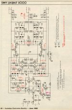
I have the schematics and pcb plans of the original aem6000 designed by Dave Tilbrook. I do not know what Suzy changed in this design. I see that she replaced through hole components with smds, which I don't like but times are changing.
Attached is the original aem 6000 diagram.
cheers,
Attached is the original aem 6000 diagram.
cheers,
Attachments
A couple of points:
1. Wayback machine is your friend.
2. I like mica caps, but NPO ceramics are just as good for the low value stuff.
3. I built mine with MELF resistors, but 1206s will work also.
4. Future electronics sells the SST404s (yay!)
5. I've had some weirdness with slow power-on due to increasing the resistors in series with the power supply for the first stage to 22R, causing big horrid DS offsets. I cured them by chucking in a pair of links in place of the resistors.
6. Watch for 2ish MHz oscillations. You'll know they're there because you burn yourself on the zobel network. You'll be fine if you stick with the standard feedback resistor values - trouble happens when trying to squeeze things")
I'm rather more relaxed about this than I was a few years ago when I first saw copied text and boards. I'm glad people are getting enjoyment from it.
1. Wayback machine is your friend.
2. I like mica caps, but NPO ceramics are just as good for the low value stuff.
3. I built mine with MELF resistors, but 1206s will work also.
4. Future electronics sells the SST404s (yay!)
5. I've had some weirdness with slow power-on due to increasing the resistors in series with the power supply for the first stage to 22R, causing big horrid DS offsets. I cured them by chucking in a pair of links in place of the resistors.
6. Watch for 2ish MHz oscillations. You'll know they're there because you burn yourself on the zobel network. You'll be fine if you stick with the standard feedback resistor values - trouble happens when trying to squeeze things
I'm rather more relaxed about this than I was a few years ago when I first saw copied text and boards. I'm glad people are getting enjoyment from it.
Hi
the first trimpot RV1 should have a value of 20kOhm according the BOM. Before mounting it should be adjusted to center value (about 10kOhm). With the trimmpot you can adjust the symmetry of the input differential amplifier to 0 mV at the output. The second trimpot RV2 is for adjusting the bias for the output FETs. I dont know exactly, what Suzy suggested, but 100 mA-120 mA per output FET is a good value.
Best regards
Gunni
Just add that the bias current you end up with is a bit of a tradeoff between THD and heat dissipation. On my 100W version I run the bias at about 100mA per transistor, which gives good THD specs. On my smaller 50W amp (one pair of FETs) I ended up winding the bias down to about 50mA, which makes the whole thing run quite a bit cooler. This was necessary because the heatsinking on the smaller amp is nowhere near as good as the big one. There's a THD hit, but not big.
Janusz is it possible for you to post the pcb plans of the original AEM6000. Or send them by PM if posting is not posible. I am toying with the idea of doing an updated pcb for through hole parts and readily available components. Some of us old guys don't do surface mount so well ( not me I love it ) and I've got good stocks of through hole parts to use up. The original pcb layout might save some time in designing a new one. On a different note its good to see you back susyj.
I just spent some time playing with the design further. Some time ago I did a second 50W version, where I omitted Q15 & Q17 on Tilbrooks original schematic. I found no appreciable difference to THD, so built a pair and have been listening to them for a few years. I didn't have any real reason to push the performance much beyond 0.001%, as the gear I had to measure with at the time (a Tek SG505 oscillator and matching THD analyser) couldn't go better than 0.001% anyway, so there was little point.
Anyway, I recently bought a Linear Tech AN67 oscillator PCB, which should be capable of generating a pure 1 or 10 KHz tone to the 1ppm level (0.0001%). I've got a lovely HP3585B spec an with a clear 100dB dynamic range at audio, and extending that 20 odd dB with a twin-t notch should be straightforward. So, 0.0001% is clearly the new 0.001%.
Based on that, I was looking at my revised schematic today and realised it's just begging for current mirror loads on the vas. I chucked some in, substituted 150MHz 2sc3503 & 2sa1381 vas transistors for the MJE340/MJE350s, bumped the bias levels up a touch to get into the sweet spot for current gain, and straight away got 0.00021% (1KHz, 50W into 8R, 1 pair output transistors and +/-40V supply), so quite some promise.
It's +2 transistors on Tilbrooks original, and -8 resistors, so fewer parts
Last edited:
Not sure I understand your current mirror mods. Did you put the mirrors in the collectors of the Q11/Q12 and Q13/Q14 pairs or do something clever with the Q15/Q16 and Q17/Q18 pairs. I thought that the latter pairs made up the VAS and can't quite see where you would put the mirrors. Maybe I'm missing something. The transistor numbers again refer to the original Tilbrook numbering. Did you use simple two transistor mirrors or something more complex like Wilson or four transistor mirrors. In my experience the latter are well worthwhile because the transfer ratio of a simple mirror isn't too great. This can lead to a lack of balance and more distortion ( allbeit small at this level of sophistication - but hey if you're chasing the last ppm ). I love to see how these amps can all be traced back to the original Hitachi design - such low distortion from such a brilliantly simple circuit.
I forgot to ask - did you see any sign of instability with your current mirror version? Some of the early Japanese designs using three cascaded differential pairs were notorious for instability, probably because they tried to squeeze out too much gain per stage. The use of mirrors will hugely increase the open loop gain of the Tillbrook design.
The mirrors go in place of R27-30. I just used straightforward 2-transistor mirrors. My reasoning was simply to increase the load impedance on q11-14, adding a touch more open-loop gain by doing so.
I'm toying with adding followers to q16 & q18 for more gate drive, but with 7-8mA running through these transistors I doubt there'll be much (if any) improvement. Indeed it'll really just add another 0.7v to the necessary headroom.
I'm toying with adding followers to q16 & q18 for more gate drive, but with 7-8mA running through these transistors I doubt there'll be much (if any) improvement. Indeed it'll really just add another 0.7v to the necessary headroom.
- Status
- This old topic is closed. If you want to reopen this topic, contact a moderator using the "Report Post" button.
- Home
- Amplifiers
- Solid State
- AEM 6000 ready to build