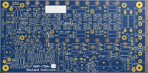
Rather than continue and extend a fragmented discussion on other threads, I'm starting a new one to discuss my amplifier design, the AMP-70. Fast slew rates are desirable for audiophile amplifiers, for better transient response. My 1000V/us amplifier, which can deliver 100W rms into 8 ohms, could be thought of as an awesome hi-fi amp, but it's really just a laboratory amplifier designed to deliver a full output swing up to 5MHz, even into capacitive loads. (I've included some reduced-size images in this post, the full versions are in the Dropbox folder linked below.)
An externally hosted image should be here but it was not working when we last tested it.
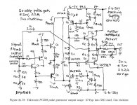
The design is based on the output amplifier in the Tektronix PG508 50MHz pulse generator. We examine this in detail as a Designs-by-the-Masters section in our upcoming book, The Art of Electronics, x-Chapters. I've included this 4-page section in the Dropbox link below. Here's the schematic.
An externally hosted image should be here but it was not working when we last tested it.
Basically there's an input stage creating a push-pull error current into a folded-cascode VAS stage, and emitter-follower outputs. The secret for fast slewing is to use a high 60mA VAS current with low Ccb capacitance transistors, for a fast slew rate S = i/C = 3000V/us for the PG508. The Tek pulse generator only had to deliver 0.2A to its load, whereas I have to deliver 5A, so I'm using larger, higher-capacitance transistors. Following the principle, F.O.M. = Pd / Ccb, to improve the slew rate, I selected low-capacitance types. They're fragile and I'm using 20, to limit their power dissipation.
An externally hosted image should be here but it was not working when we last tested it.
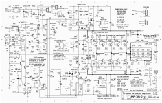
My amplifier design is somewhat more complicated, with various features to increase its capabilities, which we can discuss. Here's a dropbox link to my AMP-70A-2 schematic and related files for you to look over. Dropbox - AMP-70_DIY
Circuit topology looks similar to this amp:
stereoplay 1988 Monoblock from Günter Mania
for schematic go to post #4 under
http://www.diyaudio.com/forums/solid-state/190380-burmester-avm-schematics.html#post2598494
Wow, thanks for the lead. That's very interesting, the complementary pair of transconductance input error stages, each using a complementary pair of BJTs, and the folded-cascode VAS stage, is the same as in my amplifier. The devices and operating currents are of course quite different.
As I mentioned, I got the idea from the 50-ohm output amplifier in the Tektronics PG508 50MHz pulse generator. It uses the same input-stage circuit. This circuit has the advantage of being very fast, because it can run at high currents and doesn't require mirrors or high-gain common-emitter stages. It doesn't have very high open-loop gain, and the folded cascode stage, with pullup resistors instead of current sources, has some intrinsic distortion. So even though it has a blisteringly-fast slew rate, an audiophile would find things to criticize. But it makes an amazing DC-10MHz lab power amplifier. Several are in use now, generating quadrature electric fields for electro-rotation experiments, running at several hundred volts (with the help of a transformer) at 2.5MHz.
My earliest copy of the PG508 manual is dated Nov, 1975. My schematic copies are rev B, dated 1980. I have a 1986 catalog with a PG507 and PG508 datasheet page. Yessir, those Tektronix engineers were pretty advanced for their time!
Sorry the pictures in post 1 are not visible any more.
You can always attach new ones
") e.g. The thread owner can always update the first message of the thread.
e.g. The thread owner can always update the first message of the thread.Me too!Ooops... then ask one of the moderators, I'm sure he/she will help
I would like to see those pictures
Wow, thanks for the lead. That's very interesting, the complementary pair of transconductance input error stages, each using a complementary pair of BJTs, and the folded-cascode VAS stage, is the same as in my amplifier. The devices and operating currents are of course quite different.
As I mentioned, I got the idea from the 50-ohm output amplifier in the Tektronics PG508 50MHz pulse generator. It uses the same input-stage circuit. This circuit has the advantage of being very fast, because it can run at high currents and doesn't require mirrors or high-gain common-emitter stages. It doesn't have very high open-loop gain, and the folded cascode stage, with pullup resistors instead of current sources, has some intrinsic distortion. So even though it has a blisteringly-fast slew rate, an audiophile would find things to criticize. But it makes an amazing DC-10MHz lab power amplifier. Several are in use now, generating quadrature electric fields for electro-rotation experiments, running at several hundred volts (with the help of a transformer) at 2.5MHz.
My earliest copy of the PG508 manual is dated Nov, 1975. My schematic copies are rev B, dated 1980. I have a 1986 catalog with a PG507 and PG508 datasheet page. Yessir, those Tektronix engineers were pretty advanced for their time!
Thanks again for sharing this amplifier, it's just about perfect for our application and doesn't require me reinventing the wheel.
We've got a nice Krohn-Hite lab amp at work, which is probably a bit overbuilt for what we do, but I remembered you posted this a while ago and happy I found it, as it looks like we need a couple more high bandwidth amps for some dielectrophoretic experiments that run from audio through a couple MHz. Will probably scale back a bit on the output devices, as I think the hardest load is closer to 250-300 ohms. Fortunately we have a bunch of 33120's laying around so I just need a buffer/amp.I have the original copy of AoE on my bookshelf, which I bought in high school. Probably time to get the update!
EDIT: PCB gerbers are in the dropbox link at the very end of the first post.
Samuel Groner has also found use for this kind of topology:
https://www.eetimes.com/document.asp?doc_id=1279853&page_number=4
Samuel Groner has also found use for this kind of topology:
https://www.eetimes.com/document.asp?doc_id=1279853&page_number=4
Last edited:
EDIT: PCB gerbers are in the dropbox link at the very end of the first post.
Thanks Anthony. My board house import complains there is no drill file in the Gerber set. Although there is a file with the .DRL suffix.
Layers seem to import and display fine.
Anyone know what Gerber format this is? RX274? Extended?
Jan
Samuel Groner has also found use for this kind of topology:
https://www.eetimes.com/document.asp?doc_id=1279853&page_number=4
I know. He wrote about it in Linear Audio ;-)
volumes | Linear Audio
Jan
Attachments
- Home
- Amplifiers
- Solid State
- Winfield's 100W DC-10MHz 1000V/us amplifier