The neck of the headphone socket on my Creek 4140s2 amp has snapped off and I would like to replace it. I have bought a socket from a local Maplin store
1/4 Inch Jack Socket 6 Pole Switched PCB Mount | Maplin
However on closer examination, there are resistors soldered to some of the pins on the existing socket, so obviously the job is not as simple as I thought.
I am confident with a soldering iron, but I know little about electronics. I was planning to work out which pin was which with a meter, but I don't really understand what is going on here.
Two questions really, if anyone knows this amp:
1) Have I bought the right part?
2) Any advice about how to proceed with this job.
")
Thanks for the reply, Mooly. Here's a photo of the existing socket.
http://i615.photobucket.com/albums/tt235/erbster_photos/2016-01-31 17.02.37.jpg
http://i615.photobucket.com/albums/tt235/erbster_photos/2016-01-31 17.02.20.jpg
The new one will physically fit in place.
I was looking for a schematic, but couldn't find one in which I could identify the headphone socket.
OK, that looks do-able then.
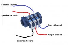
The Maplin part has 6 pins.
With no headphone plugged in, each pair of pins (right to left) has continuity.
When you plug the 'phones in, the plug lifts the contacts up breaking continuity from right to left across each pair.
You need to identify the five wires in your pictures. The one in the middle of the existing socket is probably ground. Confirm it connects to the chassis (continuity check).
One of the other four should go to the left positive speaker terminal. Confirm and note which it is.
Another should go to the right positive speaker terminal. Confirm and note which it is.
The other two will go to the left and right amplifier outputs on the circuit board.
You connect the new socket as follows. Identify which row of pins is the 'input'. From the Maplin picture it looks as if it is the right hand side. This connect to the amplifier side of things.
Before switching on and with no 'phones plugged in, check that there is continuity from the L and R amplifier outputs (on the circuit board) to the speaker sockets.
Attachments
Cheers for that detailed explanation Mooly!
The tails on the socket are quite short and will barely reach. They also pass underneath the board, so it looks like I might need to remove the board from the chassis in order to carry out the tests you outline here. I will proceed cautiously, many of the parts on this 30 year old amp are pretty brittle now!
The tails on the socket are quite short and will barely reach. They also pass underneath the board, so it looks like I might need to remove the board from the chassis in order to carry out the tests you outline here. I will proceed cautiously, many of the parts on this 30 year old amp are pretty brittle now!
I've not perhaps given you the best advice here.
There is going to be a problem when using low impedance headphones because they are going to be effectively connected across the amplifier output. Not good !
Thinking more about this, and I can't see a way to overcome this problem completely using the socket you have.
If you look at my diagram above then you can see that connecting the headphones breaks the continuity of the speaker circuit and in doing so applies the amplifier output to headphone outlet. That's only going to be suitable for high impedance headphones, and the majority of todays are low impedance.
The only solution (and its imperfect) I can think of is to wire the socket the other way around such that the amplifier feed comes in at the 'left' and outputs to the speakers at the 'right'. That would should give a scenario of the speakers falling silent when the headphones are plugged in.
In order to get audio to the headphones you would need to bridge each pair of contacts on the socket with a resistor but the problem is that the speaker would then be in the circuit via the resistor and so produce low level audio. Further to that, the headphones would then effectively be in parallel with the speaker and so not get a true 'voltage feed' which could alter there perceived sound quality.
The only other way I can think of to overcome this, is for you to fit a speaker switch either on the amp somewhere (which means drilling a hole) or in the speaker leads. The headphone socket could then be wired permanently as a normal headphone feed with its appropriate resistors and the speakers turned on/off via the switch. If the mounting of a small switch is possible then the wiring of it all is simple.
Apologies again for not spotting that at the time.
- Status
- This old topic is closed. If you want to reopen this topic, contact a moderator using the "Report Post" button.
- Home
- Amplifiers
- Solid State
- Creek 4140 headphone socket