Hello -
I think what he means is some type of circuit that could "multiply" the value of a given inductor. This would be especially useful when trying to build an inductor-input power supply filter. Normally the required inductor is so large and heavy that it roughly doubles the overall cost of the power supply. If there were a clever way to use a "small" inductor and "multiply" its action, then you could make an inexpensive amplifier that had inductor-input power supply filtering.
Unfortunately, this is just a wild goose chase.
A "capacitance multiplier" only mimics one aspect of a capacitor -- it's tendency to oppose a change in voltage. However, a "capacitance multiplier" does *not* multiply the energy stored in a capacitor. (If it did, then we could get rid of all the big capacitor banks typically found in high-quality amplifiers.)
So the analog to a "capacitance multiplier" would be a circuit that tends to oppose changes in current -- i.e., a constant-current source. However, this circuit doesn't increase the energy storage. You would still need a big inductor that would store enough energy to supply a constant charging current to the filter caps.
I think the confusion begins with the misleading term "capacitance multiplier".
Hope this helps,
Charles Hansen
Hello -
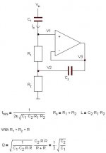
You can ignore my previous post. It looks like jackinnj was right and that millwood wanted a gyrator. Here's one link:
http://www.epanorama.net/documents/telecom/gyrator.html
Best regards,
Charles Hansen
You can ignore my previous post. It looks like jackinnj was right and that millwood wanted a gyrator. Here's one link:
http://www.epanorama.net/documents/telecom/gyrator.html
Best regards,
Charles Hansen
Charles Hansen said:Hello -
You can ignore my previous post. It looks like jackinnj was right and that millwood wanted a gyrator. Here's one link:
http://www.epanorama.net/documents/telecom/gyrator.html
Best regards,
Charles Hansen
that's the same set-up as the one using op-amp. Has anyone actually used such a circuitry?
Re: Gyrator
a gyrator is used to make the RCL transform from active xo to passive
JensRasmussen said:Hi,
I use the gyrator for making EQ's in my active x over.
a gyrator is used to make the RCL transform from active xo to passive
Re: Re: Gyrator
Hi,
passive to active or active to passive does it really make much difference. The circuit I posted acts like an RCL series connection, with the component sizes as noted.
Well I use it in a voltage devider and in the feedback of opamps as a frequency dependent resistor, This creates an EQ..... works great too
\Jens
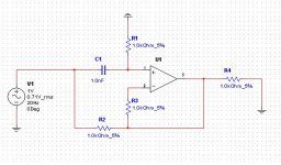
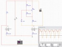
it seems to have worked in my simulation.
the left side is essentially a traditional L/C circuitry and the right side the "inductance multiplier". one big draw back for the inductance multiplier is its heavy internal resistance (thus voltage drop).
the left side is essentially a traditional L/C circuitry and the right side the "inductance multiplier". one big draw back for the inductance multiplier is its heavy internal resistance (thus voltage drop).
Attachments


Millwood,
here a good link to designing gyrator for graphic equalizers.
http://www.rane.com/pdf/constanq.pdf
I use a Gyrato years ago for the filtering the output of a DAC. It just did not sound as good as a simple RC filter which I replaced it with. Also it just used to many parts.
here a good link to designing gyrator for graphic equalizers.
http://www.rane.com/pdf/constanq.pdf
I use a Gyrato years ago for the filtering the output of a DAC. It just did not sound as good as a simple RC filter which I replaced it with. Also it just used to many parts.
- Status
- This old topic is closed. If you want to reopen this topic, contact a moderator using the "Report Post" button.
- Home
- Amplifiers
- Solid State
- inductance multiplier