Hi,
I'm thinking about building a new preamp, and want it to be fully operatable by remote control. For this everything should be controlled by a uC.
I'll most probably use relays for input selection and CS3310/PGA2310/DS1808/WM8816 as volume control. Or maybe I'll use shunt resistors for attenuation, possibly using SSM2404 switches.
Anyways, the attenuator problem is throughly discussed in the forum, but I'd also like my preamp to offer tone controls.
How do I make this digitally controlled? If I was to use digital pots, what kind should I use? I can't use any of the volume chips as pots in a Baxandall circuit, can I? Maybe there are other kinds of circuits I should look into - like bandpass filters with separate attenuators? This, however, would make each band flat internally, as opposite to the curve given by Baxandall.
I hope you guys have a few good suggestions and views on this matter. Has anybody got any experience with remote controlled bass/treble circuits?
Regards,
Truls
Have a look at http://www.maxim-ic.com/DigitalPotentiometers.cfm
They make digital linear potentiometers, like the (stereo) DS1867.
Steven
They make digital linear potentiometers, like the (stereo) DS1867.
- Nonvolatile version of the DS1267
- Two 256-position digital potentiometers
- Wipers digitally set and read through serial port
- EEPROM maintains settings in the absence of power
- Resistors can be connected in series for higher total resistance
- Ultra low-power consumption, quiet, pumpless design
- Three-wire serial control interface
- Operating ranges:
- Single +5V or ±5V supplies
- -40°C to +85°C
Steven
Thanks, but will any digital pot be good enough for audio usage? I mean there has to be a reason why there are special chips for volume control (like CS3310).
Besides, all the digital pots from Maxim has 20% or worse resistance tolerance. That can't be good. How would AD5203 compare to DS1867?
So, is the preferred method for a digitally controlled tone control to use normal dig pots in a Baxandall circuit? What would the ultimate digital pot for this be?
Cheers,
Truls
this one looks good
http://www.analog.com/Analog_Root/productPage/productHome/0,2121,AD5228,00.html
http://www.analog.com/Analog_Root/productPage/productHome/0,2121,AD5228,00.html
Most circuits with dig pots or switches take care that the signal across the pot or switch is low to avaoid distortion due to on-resistance modulation. One way to do that is to have one terminal at gnd potential and/or using the variable element at the virtual gnd input of an opamp. Presumably, with tone controls, that may not be possible, meaning that the variable element will see widely varying signal levels wrt the supplies. So, you will have quite higher THD compared to the use as level/volume control.
Jan Didden
Jan Didden
Right, and does anybody have a solution to this, or do I have to accept that the pots in a tone control circuit will make alot more noise than in an attenuator?
I was thinking of using this baxandall circuit by Rod Elliott because I like it for using two 100k pots. Most tone controls use different value pots, which makes it hard to implement with digital potmeters. I'm open for other types of tone controls as well, but this is the most appropriate baxandall circuit I've been able to find.
What should I look for when selecting a dig pot to use for this?
Any suggestions for a different approach?
-truls
Hi, how about using an analoge mux to allow you to select from a number of fixed resistors in the circuit? This owuld depend on how the mux chip delt with the unselected inputs, and would only allow a few variables, but you should be bale to find some good quality ones out there which won't mess with the sound of the signal too much.
Too bad Jan, but I found something that might look like what you were thinking of. Have a look at page 8 of the schematics document for Rane Corporation's MP 2016 Rotary Mixer. To me this looks like a low-pass, a band-pass and a high-pass filter, with one attenuator each, followed by a summing amplifier to mix the three parts together again.
This tone control is patent pending and is described in Dennis Bohn's article Accelerated Slope Tone Control Equalizers.
There's one thing about this tone control that troubles me, though. Since the filters can't be ideal, some parts of the signal will be removed even before the attenuators, or am I missing something here? Maybe I just revealed that I don't know the first thing about tone controls? :-/
-truls
bigparsnip said:Hi, how about using an analoge mux to allow you to select from a number of fixed resistors in the circuit? This owuld depend on how the mux chip delt with the unselected inputs, and would only allow a few variables, but you should be bale to find some good quality ones out there which won't mess with the sound of the signal too much.
It doesn't really make much of a principle difference whetther you use muxes or switches in this context. The point being that all ss switches suffer from on-resistance modulation by the signal. This means that the on-resistance varies with signal level, causing distortion.
The usual remedy is using them in such a topology that the signal level across the on-switch is very low, for instance by using the switch on the neg input of an inverting opamp. That input is at virtual earth so has extremely low signal level (often < 1mV). For the tone controls, this cannot be done (I mean, I don't know how to do it, maybe someone else does?). So, using ss switches as variable pots in tone controls (including ss pots) causes appreciable THD compared to mechanical switches or relays.
Jan Didden
BoGoMiPz said:Too bad Jan, but I found something that might look like what you were thinking of. Have a look at page 8 of the schematics document for Rane Corporation's MP 2016 Rotary Mixer. To me this looks like a low-pass, a band-pass and a high-pass filter, with one attenuator each, followed by a summing amplifier to mix the three parts together again.
This tone control is patent pending and is described in Dennis Bohn's article Accelerated Slope Tone Control Equalizers.
There's one thing about this tone control that troubles me, though. Since the filters can't be ideal, some parts of the signal will be removed even before the attenuators, or am I missing something here? Maybe I just revealed that I don't know the first thing about tone controls? :-/
-truls
This is an interesting article and design. I met Dennis Bohn some years ago, smart guy.
I'm not sure I understand your last point. Filters are supposed to some extend to remove parts of the signal (depending on freq). Or am I misunderstanding you?
Jan Didden
Originally posted by janneman
I'm not sure I understand your last point. Filters are supposed to some extend to remove parts of the signal (depending on freq). Or am I misunderstanding you?
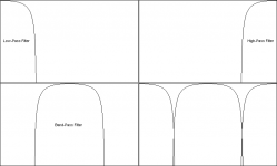
Ok, time for drawing. In the very unprofessional Paint-powered drawing below you see examples of the frequency responses for the three filters. The fourth section (in the bottom right corner) simply shows the three parts combined.
The output of each filter is some part of the original signal. After the filters comes a summing amplifier (let's assume we have 0dB here), which means that if any part of the signal is let through by two of the filters it will be amplified. If the filters were perfect and didn't overlap or have gaps between them, their outputs added together would yeild the same signal as the original. If two of these perfect filters did overlap, the overlapping frequency-band would get exactly 6dB gain when the outputs were added together. A "gap" would make this band disappear from the output entirely.
In the picture below, however, the filters are not ideal, so there are frequencies that neither fully pass through nor are fully removed by the filters. This attenuates some parts of the signal, so when you add them together you have a signal where some frequencies are weakened. There are also overlapping parts, but these don't even make up for the loss.
The way I see it, the circuit shouldn't modify the signal at all if it didn't have the attenuators after each filter. So my point is that the three filters followed by a summing amplifier (with zero gain) will alter some frequencies, because the filters are not perfect.
Please clarify if I'm wrong here.
-truls
Attachments
BoGoMiPz,
If you derive the bandpass section from the original signal by subtracting the high pass and the low pass parts from the original, then adding the three bands together will give a perfect equivalent of the original signal again. Forget about distortion and noise for the moment.
Then the use of volume controls as tone controls is an option.
I'm sure though that there are other circuits for tone controls that can use potentiometers where the absolute value of the potentiometer is not relevant, only the ratio. I only have none at hand. If time permits I will look around.
In car radio amplifiers currently small DSP circuits are used, a single IC with ADC, DSP for volume, tone control, dynamic bass boost, etc. and DAC. Although very practical in volume electronics, it is not very hi-end audio.
You can also have a look at how DC-controlled tone/volume control ICs were built; these were very popular in consumer electronics, because of the possibility for remote control, in times that digital potentiometers with built-in EEPROM were not available.
Steven
Originally posted by Steven
If you derive the bandpass section from the original signal by subtracting the high pass and the low pass parts from the original, then adding the three bands together will give a perfect equivalent of the original signal again. Forget about distortion and noise for the moment.
Then the use of volume controls as tone controls is an option.
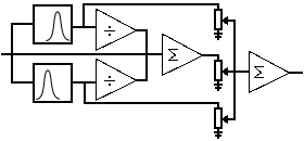
True, if this is feasible then I'm convinced. I guess it could be done like in the drawing below (details left out).
In the MP 2016 Rotary Mixer, the band-pass filter seems to be a low-pass followed by a high-pass. Is this band-pass filter so well designed that it really gives the inverted frequency response of the other two filters? I mean, does it give as good a result as the approach suggested by Steven?
-truls
Attachments
In order to see if the XP2016 BP, LP and HP sections add to a flat passband, just do a simulation. Feed it with a square wave and see if a square wave comes out again, without ringing, slow transients or overshoots.
Another way to make a 3-way section that should add up to flat is making use of a state variable filter. At least that is what I remember of it.
See e.g.
http://www-k.ext.ti.com/SRVS/Data/ti/KnowledgeBases/analog/document/faqs/spexpert.htm
http://www.maxim-ic.com/appnotes.cfm/appnote_number/1762/ln/en
For just bass and treble you can give the BP a fixed attenuation.
Steven
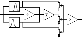
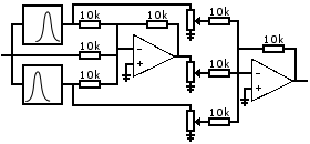
After looking a bit more on the circuit I posted earlier, I realised that the inverting buffer isn't necessary if the filters are inverting. So with inverting LP and HP filters the circuit could be built as shown below. Do you think this would work well? There are three things I'm not sure about:
1) Will the signals from the filters be messed up because of the first summing amp, or will the resistors make sure they aren't?
2) Is it ok to use the attenuator from this thread for the three pots?
3) Are the filters going to introduce a phase shift and what effects will that have when the three bands are mixed together at the end?
-truls
Attachments
Ad 1. If your filters are built around opamps they will have low output impedances and adding via resistors will not affect the filter characteristics.
Ad 2. Yes, that will work. But probably there are easier ways making a tone control when you have decided to use relays for switching anyway.
Ad 3. The filters will introduce a phase shift if they do not add up to a flat frequency response, but also a Baxandall tone control or any other minimum-phase circuit will do. As long as you are not using all-pass filters (which are non minimum phase) all filters have a fixed relationship between the amplitude response and the phase response, called the Hilbert transform if I remember correctly. So, as soon as you introduce a non flat frequency response, you get phase shift.
Steven
Thanks for the answers Steven.
What I meant by question 1, however, was if the signal to the top-most attenuator would be different from what the filter tries to output (yes I was thinking active filters). You might have answered that already, but I'm not quite sure")
I'm not sure I see how you suggest the relays can be used in a simpler way. I was planning on using this as a combined tone and volume control. 1dB steps is a requirement. The way I was thinking, all three pots would be in the same position if the (virtual) tone controls were flat. When the (virtual) volume changes, all three pots move. With separate tone and volume controls, the tone control usually has 6dB (or 12dB or whatever) attenuation when flat. The combined approach might be a bad idea. In that case I think I'll reconsider the whole thing.
-truls
What I meant by question 1, however, was if the signal to the top-most attenuator would be different from what the filter tries to output (yes I was thinking active filters). You might have answered that already, but I'm not quite sure
I'm not sure I see how you suggest the relays can be used in a simpler way. I was planning on using this as a combined tone and volume control. 1dB steps is a requirement. The way I was thinking, all three pots would be in the same position if the (virtual) tone controls were flat. When the (virtual) volume changes, all three pots move. With separate tone and volume controls, the tone control usually has 6dB (or 12dB or whatever) attenuation when flat. The combined approach might be a bad idea. In that case I think I'll reconsider the whole thing.
-truls
- Status
- This old topic is closed. If you want to reopen this topic, contact a moderator using the "Report Post" button.
- Home
- Amplifiers
- Solid State
- Digitally controlled Baxandall?