In my experience whoever said using dual drivers will give result to instabilities and more sensitive to pcb routing. Thats why I have asked in simulation i dont see any oscillations.NO, you do not want to accuse vzaichenko and jwilhelm of publishing unstable amplifier designs, do you?
Best regards!
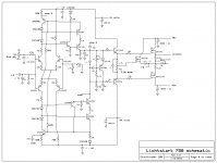
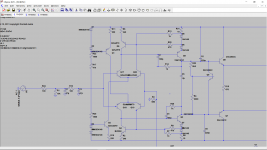
Hi Valery, trying various compensation capacitors in Lichtstark amplifier.
1. 150 pf on both sides of the VAS stage, stable to gain of 10
2. 2*22pf from VAS to 820 ohm resistor and 2*47pf on VAS to ground, stable to gain of 2.
Which of these provides the best results?
Hi! 2-nd option is better. VAS to ground can be increased to 2*100pF for even better stability without compromising the quality.
This looks like some local issue (probably layout-related), as the global loop stability parameters look good in any case - phase margin is 90-92db, gain margin is 24-27db.
Hi Valery, trying various compensation capacitors in Lichtstark amplifier.
1. 150 pf on both sides of the VAS stage, stable to gain of 10
2. 2*22pf from VAS to 820 ohm resistor and 2*47pf on VAS to ground, stable to gain of 2.
Which of these provides the best results?
any high speed designs are very much prone to oscillations. Sometimes even after varying the compensation caps. pcb routing makes very critical for parasitcs resulting in stability problems.
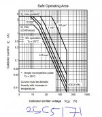
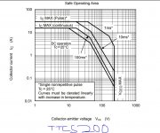
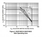
looking at the datasheets of 2sc5171 and ttc5200 the actual SOA is checked and to my surprise the output current is at 0.2Amp at 80V for a duration of non repeating 1ms signal. So considering the beta of the OPS transistors being 50 the current of 0.2A x 50 resulting in about 10Amps. Taking a 10ms pulse which is 0.05A resulting in 2.5Amps which is way too low. I agree the fact about non repeating pulse but if you look at the true performance of the driver itself i believe its not good for driving more than one or two pairs at max. Consider using a subwoofer frequency the driver cannot deliver enough current to drive the OPS effectively. I think what Valery did is right is to use dual driver stage to drive the OPS but I would still prefer other drivers to get better current delivering capability like MJE15032 and MJE15033. If you look at the SOA of the device for a 250ms signal its capable of giving 0.4Amps so even if you consider beta of 50 for the OPS its capable of delivering current as much as 20Amp into load for a lower output impedance. I think the Cob of the MJE15032 and 33 are higher might effec the distortion as capacitive load in the driver stage and they are not mentioned in the datasheet as well. I was checking the driver stage of Krell FPB 300C and 600C as I see there are two MJ3281 are driving 5 output transistors of MJ3281. I think valery was right in choosing the double driver stage.
Attachments
Last edited:
what I see is krell did a overkill by using two MJ3281 as drivers which results in excessive cob of 600pf each for the VAS to drive. Looking at the other parts of the schematic there were multiple pre driver transistors in parallel I think by using that way its able to drive the ops effectively? and also reduces the noise by some factor by paralleling.
But valery can you tell us what if we use multiple pre driver transistors and one output transistor as driver to drive 5 or 6 pairs of output transistors to drive subwoofers. Will that work without overloading the earlier stages of the amp? Like consider using 8 transistors in parallel in the output of VAS like 1381 transistors to drive a large driver transistor like 1381 and then let that 1381 drive all the other 5 or 6 ops transistors.
But valery can you tell us what if we use multiple pre driver transistors and one output transistor as driver to drive 5 or 6 pairs of output transistors to drive subwoofers. Will that work without overloading the earlier stages of the amp? Like consider using 8 transistors in parallel in the output of VAS like 1381 transistors to drive a large driver transistor like 1381 and then let that 1381 drive all the other 5 or 6 ops transistors.
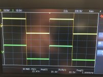
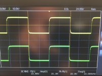
Hi Valery, What bias voltage are you using on Vhex+ ? . I am at 6.8v accross the gates , at this level a small amount of crossover distortion is visible at 20khz.
If I raise the bias to 7.25v it disappears. as this is higher then I expected, does cross conduction become a problem?
If I raise the bias to 7.25v it disappears. as this is higher then I expected, does cross conduction become a problem?
Hi Valery, What bias voltage are you using on Vhex+ ? . I am at 6.8v accross the gates , at this level a small amount of crossover distortion is visible at 20khz.
If I raise the bias to 7.25v it disappears. as this is higher then I expected, does cross conduction become a problem?
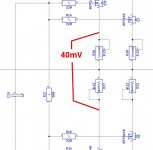
Hi! You will set the bias more precisely if you set the idle current through the output transistors. You can do it, measuring the voltage across the source resistors (Vs). For better accuracy, it makes sense to measure across two source resistors in series (see the picture attached).
Optimal idle current for this configuration = 90mA per output pair.
Vs = 90mA * 0.44 ohm = 40mV (roughly).
As soon as the OPS warms up, the Vs may slip a bit - just readjust it after some 20-30 minutes of warming up.
That's it - the bias is optimal now (you will most likely see more than 8 volts between the gates). No crossover distortion will be observed.
Cheers,
Valery
Attachments
40mV across the output resistors requires 8.1v bias. works great at this level I have yet to test it hot.
DN2540 depletion fet ( TO-220) reduces crossover distortion to barely visible with only 4v bias. 750 ohm to P channel driver 1.5k to N channel Driver to gate of DN2540. 6.8 ohm from source to output. Drain to +supply.
it may improve THD at 8v bias however I can't see it on the scope.
DN2540 depletion fet ( TO-220) reduces crossover distortion to barely visible with only 4v bias. 750 ohm to P channel driver 1.5k to N channel Driver to gate of DN2540. 6.8 ohm from source to output. Drain to +supply.
it may improve THD at 8v bias however I can't see it on the scope.
Last edited:
40mV across the output resistors requires 8.1v bias. works great at this level I have yet to test it hot.
DN2540 depletion fet ( TO-220) reduces crossover distortion to barely visible with only 4v bias. 750 ohm to P channel driver 1.5k to N channel Driver to gate of DN2540. 6.8 ohm from source to output. Drain to +supply.
it may improve THD at 8v bias however I can't see it on the scope.
At this bias setting, VHex+ measures for THD (1KHz) at around 0.005% (20V RMS @ 8 ohm) - you will not see anything in the crossover region in this case, it looks like an ideal sine wave on a scope.
Need an audio analyzer to see the spectrums then
")
Running Litchstark at 44v. mosfet outputs at 40v volts.
modified regulator so that 120hz (rectifier) noise is below amp noise. tested at NFB gain = 3000, amp still sounds good here.
Amazing performance, no sibalance on vocals even with treble maxed. easy amp to listen to.
This project has required more work then I thought.
Outstanding Work Valery!!
modified regulator so that 120hz (rectifier) noise is below amp noise. tested at NFB gain = 3000, amp still sounds good here.
Amazing performance, no sibalance on vocals even with treble maxed. easy amp to listen to.
This project has required more work then I thought.
Outstanding Work Valery!!
Running Litchstark at 44v. mosfet outputs at 40v volts.
modified regulator so that 120hz (rectifier) noise is below amp noise. tested at NFB gain = 3000, amp still sounds good here.
Amazing performance, no sibalance on vocals even with treble maxed. easy amp to listen to.
This project has required more work then I thought.
Outstanding Work Valery!!
Thank you for the build with attention to detail
Lichtstark is also based on current mode amplification, utilizing the "audio-grade" high-precision current mirrors. Fast and very accurate "music instrument"
P.S. By the way - can you drop your "as built" schematic, please.
Last edited:
Have you tested thiese "mirrors" with different current mirror gain ?72 volts p-p good for 80w RMS single channel before clipping distortion.
10% bass clipping has very little sonic effect on the rest of the passband.
Outstanding performance.
I tried different values up to a ratio of 15X ( 8.2 as drawn ) while testing various compensation for 15 - 20mhz oscillation. 22pf from vas to 820 ohm resistor stabilizes this.
I may be unstable as my layout is very tight with small traces and low capacitance.
It now only has a slight notch coming out of clipping at 20khz. this may be specific to the 3904/3906 transistors I used. The regulated higher VAS rails I am using have no effect on the waveform, just higher audio output power levels from the main supply rails.
Still Revisting the 70's
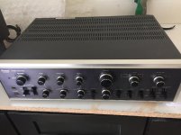
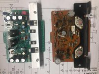
I put Valery’s Tribute 3000 driver board on a Sansui AU-9500 plug-in driver board, changed Sansui’s original T03 output transistors to NJW1308G and NJW3281G changed the emitter resistors to .22 ohm as in Valery’s Tribute OPS but only 2 output pairs instead of 3.
The Sansui has separate transformer windings of 49v for the left and right outputs and a regulated 60V supply for the driver boards.
All the supplies still have the original 45 year old capacitors and components when I did the testing.
Measuring the voltage @ the load I calculate 99.4W per channel before clipping. Definitely worth changing out the old components.
Attachments
- Home
- Amplifiers
- Solid State
- Revisiting some "old" ideas from 1970's - IPS, OPS