Are you correctly thinking through the route of the fault current?
The Drain/Collector of a Follower output stage is connected to the supply rail.
If that Drain/Collector gets shorted to the heatsink which in turn is connected to the PSU Zero Volts, then the fault current goes straight through metal contacts from supply rail to Zero Volts. No semi-conductors are in that route.
The close rated mains fuse will blow pretty rapidly, before a fire has started.
The blowout was through two devices, so the heatsink was likely not grounded. It looked like a rail to rail failure. In any case it would be hard to say what the output voltage of the amplifier would be with rails shorting out, so the protection system likely saved his tweeters and shut down the amp before too much damage occurred.
Correct about the heatsink not being grounded. The two devices that were damaged were right next to each other. One N channel and one one P channel. I assume rail to rail short circuit. The protection tripped and showed dc offset. There was a loud snap noise but I can't say if it was from the speaker or the arc itself. The fuse in the negative rail was blown but the positive rail fuse and the mains fuse were intact.
Normally one grounds the heatsink to the metal chassis even if the chassis is floating from earth ground, so the chassis/heatsink is usually at circuit ground potential. Some designs with no emitter/source R allow the HS to be at the speaker potential. For higher voltage rails it can be a shock risk.
In Evans case he is using a wood case which I recall I cautioned many threads ago as potentially being a fire hazard. One usually designs for a worst case scenerio and with UL/CSA etc in mind. I do have to wonder how is it different from a piece of gear with a wood bonnet.
I am not coming down on you Evan, but I want to make sure you and all of us fully understand what the implications are for the implementation, pretty or not. The last thing we all want is anyone to get hurt or damage to property. Safety always first.
Other than the above safety cautionary notes, what are the implications of having a floating heatsink? EMI/RFI susceptibility comes to mind, but is the heatsink or this design subject to these issues if it is floating?
In the past we used to use the BBQ starter/sparker as a test generator, to do a quick test for susceptibility. We also used to key up a RF transmitter like a hand held walky- talky that puts out around 3/5W of RF in the VHF/UHF freq range.
Now I do not expect Evan to be the QA/regulatory EE on this design, just throwing out some thoughts to discuss if it suits the members.
Of course you want to have a dummy load for these sort of tests. And your fire extinguisher handy")
What do the rest of you think about a floating heatsink or anything else I have brought up in discussion? You can tell me to shut up too, I am fine with that as I have said what I have to say now, I am cool
In Evans case he is using a wood case which I recall I cautioned many threads ago as potentially being a fire hazard. One usually designs for a worst case scenerio and with UL/CSA etc in mind. I do have to wonder how is it different from a piece of gear with a wood bonnet.
I am not coming down on you Evan, but I want to make sure you and all of us fully understand what the implications are for the implementation, pretty or not. The last thing we all want is anyone to get hurt or damage to property. Safety always first.
Other than the above safety cautionary notes, what are the implications of having a floating heatsink? EMI/RFI susceptibility comes to mind, but is the heatsink or this design subject to these issues if it is floating?
In the past we used to use the BBQ starter/sparker as a test generator, to do a quick test for susceptibility. We also used to key up a RF transmitter like a hand held walky- talky that puts out around 3/5W of RF in the VHF/UHF freq range.
Now I do not expect Evan to be the QA/regulatory EE on this design, just throwing out some thoughts to discuss if it suits the members.
Of course you want to have a dummy load for these sort of tests. And your fire extinguisher handy
What do the rest of you think about a floating heatsink or anything else I have brought up in discussion? You can tell me to shut up too, I am fine with that as I have said what I have to say now, I am cool
rsavas, no worries I am always up for learning/discussing. I could be very wrong but I don't see how the wooden chassis could be a fire hazard. In normal operation there is nothing hot enough to start a fire. If there is a problem it seems that a fuse would blow long before things would burst into flames. The plywood that these cases are constructed from does not burn very easily. It would take a lot more then a momentary spark to light them up.
I suppose if one output transistor was to short to the ungrounded heatsink then the sink could be at plus or minus 70 volts referenced to ground. I don't know would you get a shock from just touching the sink in this case or would you have to, at the same time, be touching ground or the opposing rail? Grounding the heatsinks would be an easy job.
Again I am always up for learning how to do things better.
Evan
Fuses take time to blow.
Fuses have a manufacturing tolerance.
Fit a T3A mains fuse and it will pass 3Aac at mains voltage almost forever.
Increase the current to 6Aac and it will blow, but can pass 6Aac for many seconds and even minutes if at the top end of the tolerances.
That T3A fuse will pass 1440W for upto a few minutes before it blows.
That is a lot of heat. It is potentially a fire, for nearby curtains/carpet/woodwork.
That is why I repeatedly refer to fitting close rated fuses to our equipment.
Take a 250VA 230Vac mains transformer. It needs T3A to start up direct on line. The above applies to heat generation during a fault condition.
Fit a close rated fuse of T1A which allows the transformer to meet all it's normal operational duties and the minutes duration current will be only 2Aac, or ~500W
If the T1A is subjected to the 6A fault current it blows in around 1 second (instead of minutes). That is where the safety is improved by close rating the fuse.
The downside is that a transformer needs a soft start to allow it to start up on a close rated fuse.
Last edited:
Fuses take time to blow.
Fuses have a manufacturing tolerance.
Fit a T3A mains fuse and it will pass 3Aac at mains voltage almost forever.
Increase the current to 6Aac and it will blow, but can pass 6Aac for many seconds and even minutes if at the top end of the tolerances.
That T3A fuse will pass 1440W for upto a few minutes before it blows.
That is a lot of heat. It is potentially a fire, for nearby curtains/carpet/woodwork.
That is why I repeatedly refer to fitting close rated fuses to our equipment.
Take a 250VA 230Vac mains transformer. It needs T3A to start up direct on line. The above applies to heat generation during a fault condition.
Fit a close rated fuse of T1A which allows the transformer to meet all it's normal operational duties and the minutes duration current will be only 2Aac, or ~500W
If the T1A is subjected to the 6A fault current it blows in around 1 second (instead of minutes). That is where the safety is improved by close rating the fuse.
The downside is that a transformer needs a soft start to allow it to start up on a close rated fuse.
The rule of thumb I've always followed for fusing here is multiply the maximum rated current by 125% to allow for inrush/starting currents. I'm not sure if that's a correct formula for electronics, but that's normal for motors in equipment.
The fire hazard is there in the form of arcing. The amount of heat generate from an electric arc is quite awesome! We use it every day to melt steel in the form of ark welding. If you blow air through an ark the air ignites and produces plasma - the plasma cutter. You've just seen the heat first hand when it charred the epoxy in your output transistors and made it conductive. It's a good idea to put a layer of non-combustible material between electronics and wood. Even a thin layer of sheet metal will dissipate the heat blast from an ark enough to stop ignition of the wood.rsavas, no worries I am always up for learning/discussing. I could be very wrong but I don't see how the wooden chassis could be a fire hazard. In normal operation there is nothing hot enough to start a fire. If there is a problem it seems that a fuse would blow long before things would burst into flames. The plywood that these cases are constructed from does not burn very easily. It would take a lot more then a momentary spark to light them up.
I suppose if one output transistor was to short to the ungrounded heatsink then the sink could be at plus or minus 70 volts referenced to ground. I don't know would you get a shock from just touching the sink in this case or would you have to, at the same time, be touching ground or the opposing rail? Grounding the heatsinks would be an easy job.
Again I am always up for learning how to do things better.
Evan
In your case having the heatsink ungrounded, and the secondary side of the transformers floating, there is no defined voltage to ground. Your rail voltage may measure 70V to the supply ground, but there's nothing stopping the supply ground from being at 1000V to earth ground, which isn't an unreal number (static electricity). The supply ground and the heatsink ground will match the voltage of the strongest external influence to it. If you touch it with your hand, the voltage will instantly match the voltage of your body. If there's a large potential difference, you get a little static shock. This is just an annoyance to a person normally, but static charges can be quite destructive to sensitive electronics.
Having heat sinks floating separate from the supply ground can allow there to be at a huge potential difference from the supply ground. The supply ground will likely be influenced by any high current carrying conductors near by, while the heat sinks may not. Having the heat sinks at a different potential from the supply ground can set off instability in the amplifier. In some of my testing with the VTrench amplifier, I had the heat sinks for the drivers at rail voltage, and it was an oscillator. If the heat sinks were at supply ground it ran too hot, but perfectly otherwise.
It's usually best to try to keep all grounds and the chassis around the same potential to keep everything happy. Any external metal should have a good connection to earth ground for protection from freak occurrences. The "what ifs" like a screw rattling out and falling on something can cause an external piece of metal to be at mains potential. The ground wire to whatever may become live would need to be able to carry enough current to blow the fuse or breaker.
Proper fusing at the power inlet of the amplifier is a good thing too. There was a major manufacturer (FPE if I recall correctly) of breaker panels who's breakers wouldn't trip no matter how much current flowed through them. In the automotive world, they would have been forced to issue a recall and replace all these defective products, but they are still out there.
Last edited:
the fuse rating for inductive loads like motors and transformers is 3times the maximum operational current.The rule of thumb I've always followed for fusing here is multiply the maximum rated current by 125% to allow for inrush/starting currents. I'm not sure if that's a correct formula for electronics, but that's normal for motors in equipment.
A 230VA 230Vac transformer has a maximum operational current of 1Aac.
The fuse for starting that transformer would be a 3A fuse.
A close rated fuse would be a 1A fuse.
You might find that the 230VA transformer will start up repeatedly over many years on a 2.5A fuse.
Try a 2A fuse and you will probably find it fails within a few weeks, or months.
Try a 1.25A fuse and it may start once, or twice and then it fails.
Try it.
For domestic audio power amplifiers and the way they demand current from the mains transformer, I find I can reduce the close rated fuse considerably (when I don't have the correct fuse rating in stock) and it can operate upto clipping with very loud music and the undersized fuse does not blow.
It's down to averaging of the current flows and what heating they generate in the fuse wire.
It's also the time it takes for fault current to heat up that fuse wire that allows the instantaneous fault current to be tens, hundreds and even thousands of times higher than the fuse rating.
The higher the fuse current the faster it blows. But it takes heat generation and time to melt the fuse wire.
Last edited:
A 3phase motor will operate reliably including start up, on far lower fuses than 3times.but that's normal for motors in equipment
Single phase motors are hard on fuses.
the fuse rating for inductive loads like motors and transformers is 3times the maximum operational current.
A 230VA 230Vac transformer has a maximum operational current of 1Aac.
The fuse for starting that transformer would be a 3A fuse.
A close rated fuse would be a 1A fuse.
You might find that the 230VA transformer will start up repeatedly over many years on a 2.5A fuse.
Try a 2A fuse and you will probably find it fails within a few weeks, or months.
Try a 1.25A fuse and it may start once, or twice and then it fails.
Try it.
For domestic audio power amplifiers and the way they demand current from the mains transformer, I find I can reduce the close rated fuse considerably (when I don't have the correct fuse rating in stock) and it can operate upto clipping with very loud music and the undersized fuse does not blow.
It's down to averaging of the current flows and what heating they generate in the fuse wire.
I agree with what you are saying about being able to run a lower rated fuse on the inlet. I just go by industry standards. Here the standard is 125% and slow blow fuses. I use Antek transformers normally and if you look at their test criteria (and if you can believe it), 125% of input current isn't an issue at all. We are on 120VAC here, so our current is double what you are accustomed to. This actually works out in our favour for selecting appropriate fusing availability wise.
A 3phase motor will operate reliably including start up, on far lower fuses than 3times.
Single phase motors are hard on fuses.
Three phase (600V) is what I'm normally dealing with here, but even for single phase we normally calculate 125% of FLA of the motor. Our standard practice is also to never run a motor at FLA too. You learn a whole new respect for grounding practices with 347V mains voltage present also.
Jeff, I gather from your post that it would be better if I connected both the heatsink and the supply ground to earth. Easily done. I would guess that since the amps I am using have the audio ground connected through opposing diodes and a resistor that a simple wire from supply ground and heatsink to the ground wire from the power inlet would be OK.
Any exposed metal (heat sink) should be connected directly to earth ground with 14AWG wire. The supply/main audio ground should be connected to earth ground through a loop breaker. This will keep the supply ground fairly close to earth ground potential, while still minimizing the chance of ground loops. I normally use a 30 amp bridge for a loop breaker with no noise.
Do you use a 30 amp rectifier bridge as loop breaker?
Yes. The 30 amp bridge is pretty standard for a loop breaker.
Earthing (Grounding) Your Hi-Fi - Tricks and Techniques
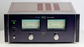
In memoriam of and inspired by the good old Sansui BA-3000
In general, I'm not a big fan of so called "blameless" topology, considering it sort of "too classic", thinking of something more "interesting", like current drive, feed-forward, etc.
However, there are some amplifiers, being a kind of a benchmark of their time. For me, one of such products is Sansui BA-3000 - a deliciously sounding bulky device, introduced in 1976, I was lucky to come across in the beginning of 80'-es. It was a real High Fidelity experience. So, I decided to play with its model, based on the modern active devices, introducing a few mods, mostly aimed to achieve very clean clipping behavior.
The model actually performed even better than I expected. Low distortion, very good profile (mostly H2 + some H3), excellent stability margins. It's definitely not the fastest one, however around 45V/uS slew rate is fine, bearing in mind all the other qualities - highly accurate clipping, symmetric rise/fall time, low noise, rather high power (200+W @ 8 ohm with +/-70V rails). Very low (among the most of my designs) ULGF = 520KHz, that still does not harm - overall "speed" of the circuit is fine.
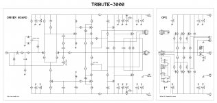
The design is rather simple, easy to layout on a single side board for etching (slowly working on it). So, I consider it as a good DIY project.
I plan to split the whole thing in 2 boards, just kind of the same way the original BA-3000 is arranged (output devices are placed on the separate board), allowing the driver board to be placed a little bit away from the heatsink.
Hi-res schematic is attached in PDF.
I can also share a Diptrace file if somebody is interested to come up with alternative layout.
Isn't it cool?
In general, I'm not a big fan of so called "blameless" topology, considering it sort of "too classic", thinking of something more "interesting", like current drive, feed-forward, etc.
However, there are some amplifiers, being a kind of a benchmark of their time. For me, one of such products is Sansui BA-3000 - a deliciously sounding bulky device, introduced in 1976, I was lucky to come across in the beginning of 80'-es. It was a real High Fidelity experience. So, I decided to play with its model, based on the modern active devices, introducing a few mods, mostly aimed to achieve very clean clipping behavior.
The model actually performed even better than I expected. Low distortion, very good profile (mostly H2 + some H3), excellent stability margins. It's definitely not the fastest one, however around 45V/uS slew rate is fine, bearing in mind all the other qualities - highly accurate clipping, symmetric rise/fall time, low noise, rather high power (200+W @ 8 ohm with +/-70V rails). Very low (among the most of my designs) ULGF = 520KHz, that still does not harm - overall "speed" of the circuit is fine.
The design is rather simple, easy to layout on a single side board for etching (slowly working on it). So, I consider it as a good DIY project.
I plan to split the whole thing in 2 boards, just kind of the same way the original BA-3000 is arranged (output devices are placed on the separate board), allowing the driver board to be placed a little bit away from the heatsink.
Hi-res schematic is attached in PDF.
I can also share a Diptrace file if somebody is interested to come up with alternative layout.
Isn't it cool?
Attachments

- Home
- Amplifiers
- Solid State
- Revisiting some "old" ideas from 1970's - IPS, OPS