Yes,amplifiers and preamplifiers everywhere.....no chassis no heatsinks......
This travel is long,too long and expensive,i believe that i must be stop because of the money.
The good news is that i have friends all over the world,they offer to me a lot of parts.
Thank to all of you")
Perhaps a "group buy" to provide some Chinese chassis' to thimios?
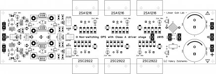
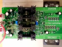
Hi All, first power-on of the non-switching OPS went well. It is under-biased so far, but it works ok in general. Hope, tomorrow I will have time to bias it properly and test the clamping mechanism.
Cheers,
Valery
I built mine but decided to stop until you had a chance to test yours. Waiting for further instructions.
Briefly tested with proper bias, one pair of output devices and briefly set bias clamping (in combination with TubSuMo front-end, adapted to +/-50V rails).
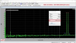
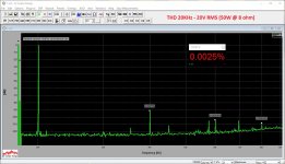
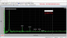
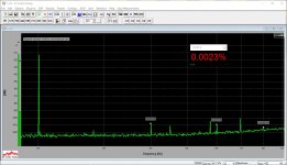
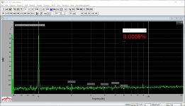
THD does not exceed 0.002% at 1KHz and 0.004% at 20KHz (20V RMS @ 8 ohm = 50W).
Wait, tomorrow I will publish the method of setting up the 2-nd spreader the right way.
Cheers,
Valery
THD does not exceed 0.002% at 1KHz and 0.004% at 20KHz (20V RMS @ 8 ohm = 50W).
Wait, tomorrow I will publish the method of setting up the 2-nd spreader the right way.
Cheers,
Valery
Member
Joined 2009
Paid Member
Perhaps a "group buy" to provide some Chinese chassis' to thimios?
Minimum effort and good price option is get some old home theatre receivers from people who love to upgrade, then you get big box, big heat sink all drilled and readY, and big power Traffo plus the box has power switch and vents. I use Pioneer chassis so my amps TGM7 and TGM8 PCB layout fits holes drilled in Pioneer heat sinks.
there are literally millions of Pioneer HT boxes out there. Much more sensible to design for them than DIY Audio heat sink hole spacing!
Last edited:
Full scale test!
Delicious
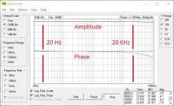
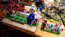
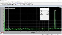
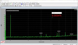
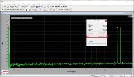
Tested and measured in combination with TubSuMo front-end, adapted to +/-50V rails (got this PSU on my test bench now).
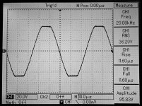
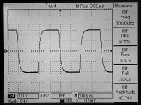
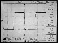
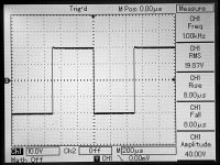
Bode, spectrums at 50W @ 8 ohm (see the IMD one!), squares, clipping.
Distortion is pretty damn low even at the higher end of the audio range.
Next post - some useful instructions for building and setting it up the right way.
Cheers,
Valery
Delicious
Tested and measured in combination with TubSuMo front-end, adapted to +/-50V rails (got this PSU on my test bench now).
Bode, spectrums at 50W @ 8 ohm (see the IMD one!), squares, clipping.
Distortion is pretty damn low even at the higher end of the audio range.
Next post - some useful instructions for building and setting it up the right way.
Cheers,
Valery
Attachments
-
 10-@Tube-Bode-12v.JPG103.2 KB · Views: 2,106
 -
 DSC_0116.JPG449.4 KB · Views: 428
 -
 DSC_0115.JPG484.7 KB · Views: 217
 -
 DSC_0113.JPG468 KB · Views: 191
 -
 DSC_0111.JPG427.8 KB · Views: 187
 -
 DSC_0110.JPG495.4 KB · Views: 244
 -
 12-@Tube-IMD-14-15k-20v.JPG289.3 KB · Views: 1,657
 -
 11-@Tube-THD-20k-20v.JPG269.6 KB · Views: 1,748
 -
 11-@Tube-THD-10k-20v.JPG268.3 KB · Views: 1,843
 -
 11-@Tube-THD-01k-20v.JPG284.7 KB · Views: 2,004
Delicious
Tested and measured in combination with TubSuMo front-end, adapted to +/-50V rails (got this PSU on my test bench now).
Bode, spectrums at 50W @ 8 ohm (see the IMD one!), squares, clipping.
Distortion is pretty damn low even at the higher end of the audio range.
Next post - some useful instructions for building and setting it up the right way.
Cheers,
Valery
Very good harmonic profile...
Building instructions
Q4 (npn in the 1-st spreader) - don't put it on a heatsink under the board. Put it vertically at the top of the board (mind the pinout, base is always marked with square plate).
R1, marked "Optional" - put 2.7k there (good for 8mA TubSuMo VAS).
R19 - NTC under the board - put it close to the board (1-2 mm from the board), it does not need to touch the heatsink, measuring the ambient air temperature.
See the trimmers orientation on the photo - R2 (on the left), trimming screw is at the bottom, R14 (on the right), screw is at the top.
Before you power it on:
1) Set the bias trimmer (R2) all the way counter-clockwise (maximum value);
2) Set the clamping trimmer (R14) in the middle position (or a bit counter-clockwise from the middle).
3) Connect the milli-voltmeter to the "BIAS" plug (200mV scale or so).
Make sure, everything is connected properly, you did not forget to connect NFB.
Power On. Now:
1) See the voltage on the milli-voltmeter, must be couple of millivilts. Rotate R2 trimmer clockwise slowly and carefully - voltage will increase, set it to 30-35 mV. Let it warm-up (10-15 minutes) and adjust again.
2) The dummy load (say, 8 ohm) is in place, send the input signal (1KHz), so that you have some 10V RMS sine at the output and leave it this way.
3) Note the voltage at your milli-voltmeter. Now start rotating the other trimmer (R14) clockwise carefully - watch the voltage at your milli-voltmeter. As soon as it starts growing a bit (plus 5 millivolts or so) - stop and leave it this way. Your clamping spreader is set to the optimum position.
Once again - you set the bias (R2) with no signal, but you set the clamping spreader with the signal constantly on.
That's it - the board setup is done.
Next post - a few amendments in TubSuMo front-end for those, who want to have a full enchilada
Cheers,
Valery
Attachments
TubSuMo amendments
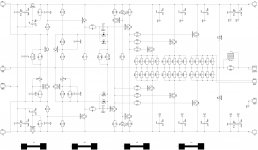
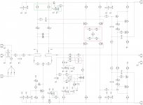
Here are the TubSuMo front-end amendments.
First of all - those need to be changed in any case for stability improvements:
1) R27-R31 - see the values on the schematic attached;
2) C18 - increase to 15pF (lead compensation).
Now, if you want to run it from +/-50V rails (instead of the original +/-70V):
1) R6 = R11 = 10K;
2) You can also remove D8, D9 zeners - they will not work properly anyway at this lower voltage.
That's it. Enjoy
Cheers,
Valery
Attachments
Q4 (npn in the 1-st spreader) - don't put it on a heatsink under the board. Put it vertically at the top of the board (mind the pinout, base is always marked with square plate).
R1, marked "Optional" - put 2.7k there (good for 8mA TubSuMo VAS).
R19 - NTC under the board - put it close to the board (1-2 mm from the board), it does not need to touch the heatsink, measuring the ambient air temperature.
See the trimmers orientation on the photo - R2 (on the left), trimming screw is at the bottom, R14 (on the right), screw is at the top.
Before you power it on:
1) Set the bias trimmer (R2) all the way counter-clockwise (maximum value);
2) Set the clamping trimmer (R14) in the middle position (or a bit counter-clockwise from the middle).
3) Connect the milli-voltmeter to the "BIAS" plug (200mV scale or so).
Make sure, everything is connected properly, you did not forget to connect NFB.
Power On. Now:
1) See the voltage on the milli-voltmeter, must be couple of millivilts. Rotate R2 trimmer clockwise slowly and carefully - voltage will increase, set it to 30-35 mV. Let it warm-up (10-15 minutes) and adjust again.
2) The dummy load (say, 8 ohm) is in place, send the input signal (1KHz), so that you have some 10V RMS sine at the output and leave it this way.
3) Note the voltage at your milli-voltmeter. Now start rotating the other trimmer (R14) clockwise carefully - watch the voltage at your milli-voltmeter. As soon as it starts growing a bit (plus 5 millivolts or so) - stop and leave it this way. Your clamping spreader is set to the optimum position.
Once again - you set the bias (R2) with no signal, but you set the clamping spreader with the signal constantly on.
That's it - the board setup is done.
Next post - a few amendments in TubSuMo front-end for those, who want to have a full enchilada
Cheers,
Valery
Hi, how it works on capacitive load (as example: square signal 20 kHz to 8 om+2,2 uF)?
Hi, how it works on capacitive load (as example: square signal 20 kHz to 8 om+2,2 uF)?
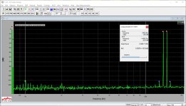
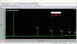
OK, tested with 0.1uF and with 1.1uF - the ones I've got in hand right now
Attachments
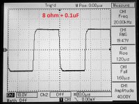
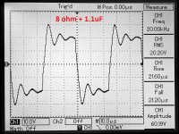
OK, tested with 0.1uF and with 1.1uF - the ones I've got in hand right now
Very big thanx for answer.
Will this OPS also work with the Slewmaster IPS at 5.5mA?
Hi Terry - yes, sure - you will need to adjust R1 to the lower value, so that the whole range, controlled by R2, will move in the right directon.
You can put a 5k multi-turn pot instead of R1. Set R2 to the center, R1 to 5k position.
Power-on, the bias will be low. Rotate R1 until you see some 30 mV across both emitter resistors. Unsolder R1, measure, and replace with the normar resistor. I think, it will be 2.2k or so. Power on again and set the bias with R2 as usual.
Cheers,
Valery
Very good amplifier.
Glad to see that all your knowledge is for sharing, not to take some money
Thank you Thimios
Delicious
Tested and measured in combination with TubSuMo front-end, adapted to +/-50V rails (got this PSU on my test bench now).
Bode, spectrums at 50W @ 8 ohm (see the IMD one!), squares, clipping.
Distortion is pretty damn low even at the higher end of the audio range.
Next post - some useful instructions for building and setting it up the right way.
Cheers,
Valery
Hi Valery!
wow!
but how about the tests lets say 1-5W 1kHz at resistive vs real speakers load?
Once you told you will make it...
Good AMP.
You asked for the spectrums with capacitive load
Same 50W output power.
Attachments
-
 11-@Tube-THD-01k-20v.JPG186.5 KB · Views: 134
 -
 11-@Tube-THD-10k-20v.JPG176.2 KB · Views: 137
 -
 11-@Tube-THD-20k-20v.JPG176.8 KB · Views: 125
 -
 12-@Tube-IMD-14-15k-20v.JPG188.6 KB · Views: 118
 -
 11-@00.JPG53.5 KB · Views: 113
 -
 02-@Tube-IMD-14-15k-20v.JPG189.4 KB · Views: 126
 -
 01-@Tube-THD-20k-20v.JPG176.5 KB · Views: 137
 -
 01-@Tube-THD-10k-20v.JPG175.7 KB · Views: 530
 -
 01-@Tube-THD-01k-20v.JPG193.1 KB · Views: 537
 -
 01-@00.JPG54.7 KB · Views: 555
Last edited:
Hi Valery!
wow!
but how about the tests lets say 1-5W 1kHz at resistive vs real speakers load?
Once you told you will make it...
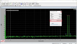
Hi Pawel,
Thanks for reminding me
Here are THD and IMD measurements for 2W @ 8 ohm.
Attachments
-
 11-@Tube-THD-20k-4v.JPG175.5 KB · Views: 126
 -
 11-@Tube-THD-10k-4v.JPG174.8 KB · Views: 134
 -
 11-@Tube-THD-01k-4v.JPG184.8 KB · Views: 128
 -
 11-@00.JPG65.2 KB · Views: 102
 -
 02-@Tube-IMD-14-15k-4v.JPG277.9 KB · Views: 124
 -
 01-@Tube-THD-20k-4v.JPG175.5 KB · Views: 114
 -
 01-@Tube-THD-10k-4v.JPG174.8 KB · Views: 133
 -
 01-@Tube-THD-01k-4v.JPG190.1 KB · Views: 121
 -
 01-@00.JPG66.3 KB · Views: 98
 -
 12-@Tube-IMD-14-15k-4v.JPG276.4 KB · Views: 117
- Home
- Amplifiers
- Solid State
- Revisiting some "old" ideas from 1970's - IPS, OPS