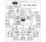
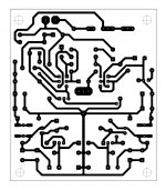
If there is interest, I've prettied up the solid state Ampliwire for etching. PDF available. PM me.
Yours is prettier than mine but mine was handy so I etched a pair from my file.
Hopefully it is correct. I got a new batch of boards and they came with a white substrate. I'm not sure yet if I am going to like it. Anyway, Now I have both sets to populate, I should get started.

Attachments
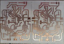
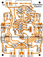
For etching, I like tiny holes that act as drill guides, big solder pads, and smooth transitions to make intersections more robust. I get really clean transfers, then I go in with a sharpie and fix the little voids and imperfections before I etch. The whole process results in amazingly nice boards. I use 2oz copper on nice thick fr4. I want to secure some paper that transfers toner more readily. I need to go buy a "Southern Living" magazine to try Pete's favorite paper.
Hi Valery,
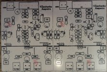
Not sure if you are following today but I populated the boards but am having trouble getting it to work. I followed the attached layout. I used MPSA18 in place of 2N5089 because I didn't have any and they look pretty close. I don't think the input pair is quite coming on. Could be something else though. Please take a look and see if I missed something.
Thanks, Terry
Attachments

I found 2N5088 ,I must ask Vallery if is it suitable for using here?Hi Valery,
Not sure if you are following today but I populated the boards but am having trouble getting it to work. I followed the attached layout. I used MPSA18 in place of 2N5089 because I didn't have any and they look pretty close. I don't think the input pair is quite coming on. Could be something else though. Please take a look and see if I missed something.
Thanks, Terry
Last edited:
I use shelving contact paper for my iron transfer. The pictures above were done that way. I had zero touch up on these. The silk was done with the same process. I don't think you can do that with paper.
Terry, does the shelving paper that you use have glue on one side ? If so, how do you get the circuit printed on the paper without the paper getting stuck in the laser printer ? The glue on the paper will get stuck due to the heat of the printer ?

Terry, does the shelving paper that you use have glue on one side ? If so, how do you get the circuit printed on the paper without the paper getting stuck in the laser printer ? The glue on the paper will get stuck due to the heat of the printer ?
You beat me to my question. Terry, Exactly what shelving paper do you use? I'm very paranoid about melting stuff into the laser printer. Thanks. I have the Ampliwire solid state and the Ampliwire Tube etched and ready to drill. Anxious to see the finished stable component values! The solid state circuit I etched is a later simpler circuit than the one you are working on. I don't know when one of the intrepid builder/testers will build/test it. When you do, I'm ready!!! In the mean time I have the Kypton ND and Borys' Tube IPS to play with. Thanks, y'all!!!
Last edited:
Terry, does the shelving paper that you use have glue on one side ? If so, how do you get the circuit printed on the paper without the paper getting stuck in the laser printer ? The glue on the paper will get stuck due to the heat of the printer ?
Sorry, I should have been more clear. I first print out the image on a plain piece of paper. Then I cut a piece of the contact paper slightly larger than the image, peel the back off and cover that image with the contact paper and run it through the printer a second time. The image is now applied to the surface of the contact paper. Next, I center the board over the image, foil side down, and tape it in place. Flip it over and apply the iron on the highest setting for about 1 to 1 1/2 minutes until I see the paper begin to tan. (This part may take a little practice depending on the temperature of your iron). Next douse the board in cold water to set the toner. Now peel away the paper and you should be left with a clean transfer with little or no toner remaining on the shelving paper. I use the same process for transferring the silkscreen image.
Last edited:
Thanks a lot, the shelving paper is glossy, is that correct ?
The one I use is made by Kittrich.com and is color marble coffee. I'm sure others will work but this one is proven to work. I buy it from the dollar store
http://www.walmart.com/ip/Con-Tact-...elf-Liner-18-x-75-Roll-Marble-Coffee/20895772
The Dollar Tree sells 1.5 yard rolls for $1
Last edited:
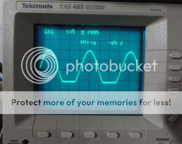
Here is scope shot of the Ampwire FET at 1.1khz. +-55v rails. ND, PD tied to the NFB.
Hi Terry,
Interesting cutting of the bottom half-wave - looks like something is wrong.
I will look at it closely tomorrow. Can you please measure the voltage across the following resistors (with no signal, schematic from post #167): R34, R20, R9, R12, R1, R3.
Cheers,
Valery
Hi Valery,
You got me looking in the right places. With all the part number changes I messed up and stuck 100R in for R1, should be 200R. Now that I have that corrected, the output looks fine. However, Now I have 18mA on the neg rail and 23mA on the pos rail. Is this normal?
Also, what is the correct method for adjusting the trimmer?
Thanks, Terry
Hi Valery,
I hooked it up to a Mini Slew OPS. I discovered that it needs close to +-50v to get the front end working. Maybe it will work on lower rails if the 6k8 resistors are lowered. Square waves look beautiful and the sound is lovely. Thanks for another great design.
Blessings, Terry
I hooked it up to a Mini Slew OPS. I discovered that it needs close to +-50v to get the front end working. Maybe it will work on lower rails if the 6k8 resistors are lowered. Square waves look beautiful and the sound is lovely. Thanks for another great design.
Blessings, Terry
Hi Valery,
I hooked it up to a Mini Slew OPS. I discovered that it needs close to +-50v to get the front end working. Maybe it will work on lower rails if the 6k8 resistors are lowered. Square waves look beautiful and the sound is lovely. Thanks for another great design.
Blessings, Terry
Hi Terry,
Great news - you are actually the first one who tested the live prototype of this front-end

My lab is coming back to life slowly but surely - many thanks for what you are doing in the meantime!
You are right - 6k8 ones were calculated based on +/-70-75V rails.
For +/-40-50V rails, the right value there would be 3.6K (also 2 of them in parallel). Otherwise, zeners get not enough current to work properly.
Cheers,
Valery
- Home
- Amplifiers
- Solid State
- Revisiting some "old" ideas from 1970's - IPS, OPS