We can figure that a part has become out of tolerance. Here are three ways to try to find the problem. The safe way is to unplug the amp and use an ohmmeter to test between various points and try to find a difference between the good amp channel and the bad one. In the olden days, curve tracers were used to do a better job at finding any small differences.
The more risky but faster way is to unhook various connections and bypass them so that you can isolate sections of the circuit. For example, you might disconnect the driver stage from the output stage. If you do it wrong, you can smoke something. absolutely use a short lamp with this method.
the last way is also risky and requires a short lamp also. Use various resistor values of about 1/10th the value of each one and lower the resistance by soldering it under the board in parallel with the one being lowered in value. Maybe in the area where the problem is the resistor will change the DC offset.
The problems are harder to solve than complete breakdown from a totally bad part. The reason is that the whole amp is a closed system with all the parts affecting the others.
Hi !!
Current feedback amps are famous for poor DC precision...usually they need a servo
See a exemple:
http://www.accuphase.com/pdf/e-212_e.pdf
Regards
Current feedback amps are famous for poor DC precision...usually they need a servo
See a exemple:
http://www.accuphase.com/pdf/e-212_e.pdf
Regards
My experience with CFB suggests that more than about 5mVDC at the output is a sign with a signal and load applied (sometimes even without a load!), it will probably break into oscillation. The cause usually a mystery and even if the problem is corrected one may still be in the dark about what and why.
Since you have one good boad, I suggest you sit down with both in front of you and systematicly check that each component is the same. Cap and transistors will just be visual checks, but you can measaure each resistor (and those are the easiest to insert a wrong value). Chances are small that you have a wrong transistor or diode backwards since that usually blows a fuse, but check anyway. Use the schematic and check continuty where ever you can; this may pick up bad solder joints.
If you turn up a blank otherwise, try flipping the board over and reflowing each solder joint.
I have a nice CFB amp that I use everyday gives me no problems, sounds great etc., etc..... but I had to take the irritating route of building four PCBs and using the two best ones. I checked and rechecked everything I could think of about the two rejects, I could find nothing different about them except fthat they didn't function correctly.
There is not necessarily any wrong or defective part.
First I would measure and compare all symmetrical voltages of the upper and lower half, that define the currents in the current sources and cascode thresholds.
It may just be a question of tolerances, especially of matching transistors and zehners in the upper and lower half.
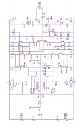
Also it could help to take out the feedback resistor and ground the joint of the emitter resistors of Q11 and Q12 (neg. in.). So you can check the static forward operating characteristic of the amp.
I would not try experiments like shorting resistors, because this may ruin everything. Also there is no point why the amp should work better with shorted components.")
And of course a dc-servo should be implemented.
First I would measure and compare all symmetrical voltages of the upper and lower half, that define the currents in the current sources and cascode thresholds.
It may just be a question of tolerances, especially of matching transistors and zehners in the upper and lower half.
Also it could help to take out the feedback resistor and ground the joint of the emitter resistors of Q11 and Q12 (neg. in.). So you can check the static forward operating characteristic of the amp.
I would not try experiments like shorting resistors, because this may ruin everything. Also there is no point why the amp should work better with shorted components.
And of course a dc-servo should be implemented.
You might want to see that your zener voltages are correct, and you can check voltages point by point between the good and bad channel and even between each half of the bad channel because it looks symmetrical. Once you localize the area of the problem, you can power the amp down and look for incorrect resistances, shorts, test for leaky capacitors & may want to try replacing a transistor or two in that area if anything looks wrong with the Vbe, etc.
lukio, since you have one channel working you know that the design has shown signs to work. That's good!lukio said:I've built my own CFB amp...in two channel for stereo. One channel runs perfectly, but the other has permanent DC offset about -4 volts. I don't know why,,,please give me advise
How about you input bias trim? Is the potentiometer in min or max? If no, I suggest that you measure interesting voltages in the feedback and the current amp. Compare with the working one and also with the theorethical values. CFB amps are a bit sensitive for unequal current gain in the transistors.
Does Miller Capacitance help
Dear every body ....
thx a lot for your answers.....
after I measure, there is voltage difference between the good one and the others. The good one has volt. diff. about 70 mv at R23, R24& R27, R28 and has volt. diff. about 1.2 V at R2 & R15 (2 ma runs) but the bad one has volt. diff. about 70 mv at R23, R24 but about 240 mv at R27,R28 and has volt diff. about 1.9 V at R2 & R15 (4 ma runs!!). If these problem caused by oscillation , does it necessary to place miller cap. between colector Q 33 and base Q5 and vice versa for Q32 & Q6?
Attachments

- Status
- This old topic is closed. If you want to reopen this topic, contact a moderator using the "Report Post" button.
- Home
- Amplifiers
- Solid State
- My CFB amp has permanent DC offset