Hi Stewart,
-Chris
It's the same for all of us. No worries.Takes alot to soak in learning new things as I get older
-Chris
Anyway, here's two "before and after" pics. Cosmetically you could call it "barn find" to "concourse level" - but regarding audio quality it is more like "beam me up".
Per
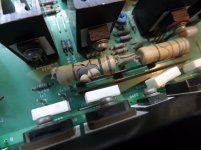
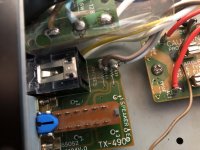
One interesting thing in the "before" picture in post #356 is the manual addition of a R-C filter between the LTP bases in this late RA-930AX production amp. Note the sharing of the LTP base pcb holes with the filter components. Would probably have been tricky in mass production.
Anyway, this filter was implemented in all later Rotel models and for good reasons. There is a nice TI article that explains the basis of such an input filter at:
http://www.ti.com/lit/an/slyt631/slyt631.pdf
What a fascinating topic!
What do you guys think about the influence of output fuses? In my 840BX4 they are outside the feedback loop so I took them out and bypassed terminals with a hefty solid copper wire. I didn't make any measurements yet but the difference can be clearly heard, especially on high volume levels when current really flows though them.
I'm not recommending it to anyone but since these fuses don't really protect speakers.. maybe it's worth trying?
The 2nd modification stage therefore was set to further steady the current supply to the input and VAS stages by improving the ripple on the DC rails.
First by filtering the input stages' positive and negative supply rails with two 100ohm/100uF/100nF lowpass RC filters and then inserting a cascode transistor in the tail-current source using the filter mod from stage 1.
Does this work? - You bet.
Stage 2 results:
Input stage rail ripple:
Reduced from 30mVac to less than 8mVac
I'm a bit puzzled about how should I incorporate the filtering mod in my 840BX4. A solid state technology is not my strong suit.
The amp has a separate B+ rail for the power amp input stage (called +B3). It's independently rectified and smoothed although the ripple is 50 mV, much higher than in its little brother 820AX. The B- rail is shared, so it complicates things for me. Also positive and negative rails are coupled by C621, to make things even harder for me to understand.
Where should I put 100 ohm resistors? Perhaps at the input of +B3 and between R627 and R673? Should I place caps as close as possible to input stage transistors or is it not necessary? On the negative rail, do I need caps also after R685 dropping resistor?
Here is the original schematic with measured ripple voltages.

Hi PakaPL,
Firstly, the RA-840BX4 is one of Rotels circuit designs which I am perhaps less familiar with. I have repaired a few, but never upgraded one with current mirrors and VAS's.
But there are definitely a few things you could do. 400mV ripple on +/-B1 is too much.
In comparison, an RA-931 has about 30-40mV ripple on its rails and a few mV after the filters.
If you haven't already done so, you could consider changing the reservoir capacitors C909/910 to modern 63V 10,000uF low ESR types that physically fits into place. And the B3 rail's C923 to a low ESR 63V rated with as much capacity as will fit onto the pcb.
Secondly, these days I don't bother with the input cascode design, the input stage filter does the job.
The easy way for you is to replace C619-622. The C619/620 with 100uF Panasonic FM's and the C621/622 with 0.47 or 1uF caps. My TM copy does not show the pcb tracks well, so you may have to find out where to drill some new 0.8mm holes in the right places to fit the caps in.
The 100 ohm resistors go in the B3 rails between the C923 and input stage rails, again, I can't clearly see where, but you will have to cut the track(s) and bridge with the 100 ohms. The negative rail already has a 120k which with a good quality 1 uF should give plenty of ripple reduction.
Remember to put in the electrolytics the right way round, or else there will be smoke.
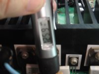
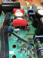
Thirdly, am I right that the power resistors R641-644 get very hot? The ones in e.g. the RA-940/960BX definitely do (126 degC), see enclosed pics. And they fry the pcb and all surrounding componets. So, in the RA-980BX Rotel removed them and reverted to the more straightforward 47 Ohms 0.5W between the two Q623/625 driver emitters. Works as a treat and stops global warming.
Remember to cover the 47 R’s in a insulating sleeve to avoid accidental shorts if mounted on the pcb track side.
Happy modding!
Cheers,
Per
Firstly, the RA-840BX4 is one of Rotels circuit designs which I am perhaps less familiar with. I have repaired a few, but never upgraded one with current mirrors and VAS's.
But there are definitely a few things you could do. 400mV ripple on +/-B1 is too much.
In comparison, an RA-931 has about 30-40mV ripple on its rails and a few mV after the filters.
If you haven't already done so, you could consider changing the reservoir capacitors C909/910 to modern 63V 10,000uF low ESR types that physically fits into place. And the B3 rail's C923 to a low ESR 63V rated with as much capacity as will fit onto the pcb.
Secondly, these days I don't bother with the input cascode design, the input stage filter does the job.
The easy way for you is to replace C619-622. The C619/620 with 100uF Panasonic FM's and the C621/622 with 0.47 or 1uF caps. My TM copy does not show the pcb tracks well, so you may have to find out where to drill some new 0.8mm holes in the right places to fit the caps in.
The 100 ohm resistors go in the B3 rails between the C923 and input stage rails, again, I can't clearly see where, but you will have to cut the track(s) and bridge with the 100 ohms. The negative rail already has a 120k which with a good quality 1 uF should give plenty of ripple reduction.
Remember to put in the electrolytics the right way round, or else there will be smoke.
Thirdly, am I right that the power resistors R641-644 get very hot? The ones in e.g. the RA-940/960BX definitely do (126 degC), see enclosed pics. And they fry the pcb and all surrounding componets. So, in the RA-980BX Rotel removed them and reverted to the more straightforward 47 Ohms 0.5W between the two Q623/625 driver emitters. Works as a treat and stops global warming.
Remember to cover the 47 R’s in a insulating sleeve to avoid accidental shorts if mounted on the pcb track side.
Happy modding!
Cheers,
Per
Attachments
Last edited:
Also positive and negative rails are coupled by C621, to make things even harder for me to understand.
I just noticed that strange connection. But is it actually connected like that on the pcb, or is it just a mistake in the schematic?
Anyway, the RC filter caps should go to ground and so you may have to re-position the negative pin of C621 to that effect.
I just noticed that strange connection. But is it actually connected like that on the pcb, or is it just a mistake in the schematic?
Anyway, the RC filter caps should go to ground and so you may have to re-position the negative pin of C621 to that effect.
No need to cut the tracks to insert the 100R resistors... the B+ is fed via two wires (A and B) to pre-amp section. Just insert the resistors in series.
It would be nice to hear of any positive outcome of this mod.... the ripple should drop substantially to less than 10mV.
It would be nice to hear of any positive outcome of this mod.... the ripple should drop substantially to less than 10mV.
Attachments
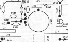
The C623/R669 pair is a pole-zero filter as described at the end of the linked TI app note in my post #363.
There are a few more strange things in the schematic, which is why I question its accuracy.
One is that the headphone output seems to be taken from inside the feedback loop - after the 120k. You wouldn't get much sound in your flappers from that connection.
Secondly, the power stage is coupled as an inverting amp, which is why the phono stage also inverts the signal through IC403. But the line preamps IC701/702 seem to be non-inverting. That can't be right.
But my grainy service manual copy does not allow me to verify.
Per
The pole-zero at diff input is okay, I do not have troubles understanding that bit.
The headphone output pickup point is an obvious error...
I will hook up an oscilloscope to figure out exactly what's going on with the feedback and in phase/out of phase input/feedback signals... can't get my head around this mess just from looking at the schematics...
What I can confirm is that just by increasing the filtering capacitors to 10,000uF/50V in all 3 positions, the ripple is reduced to 70mV on the output stage rails, and 7mV on the input stage rails.
Thank you for all the hints!
I'll verify my measurement, It's possible I messed up with probe attenuation.
Yes, I can confirm this connection is true to the PCB. I'll try to move C621 to ground and solder electrolytics in parallel.
Regarding the inverting or non-inverting stages, my knowledge is lacking here but I can supply you with a good copy of the service manual. I'm pretty sure that pinout of all ICs is true to the schematic.
Does it matter what's the phase of a signal that feeds the power amp?
But there are definitely a few things you could do. 400mV ripple on +/-B1 is too much.
In comparison, an RA-931 has about 30-40mV ripple on its rails and a few mV after the filters.
I'll verify my measurement, It's possible I messed up with probe attenuation.
I did exactly that. I have a couple o thoughts about cap replacement, different op amps and op amp supply voltage alteration. More on this later.If you haven't already done so, you could consider changing the reservoir capacitors C909/910 to modern 63V 10,000uF low ESR types that physically fits into place. And the B3 rail's C923 to a low ESR 63V rated with as much capacity as will fit onto the pcb.
The easy way for you is to replace C619-622. The C619/620 with 100uF Panasonic FM's and the C621/622 with 0.47 or 1uF caps. My TM copy does not show the pcb tracks well, so you may have to find out where to drill some new 0.8mm holes in the right places to fit the caps in.
I just noticed that strange connection. But is it actually connected like that on the pcb, or is it just a mistake in the schematic?
Anyway, the RC filter caps should go to ground and so you may have to re-position the negative pin of C621 to that effect.
Yes, I can confirm this connection is true to the PCB. I'll try to move C621 to ground and solder electrolytics in parallel.
As Extreme_Boky noted, it's possible to put these resistor in series with feeding wire. A proper mounting on a PCB is almost impossible due to limited space.The 100 ohm resistors go in the B3 rails between the C923 and input stage rails, again, I can't clearly see where, but you will have to cut the track(s) and bridge with the 100 ohms.
Yes, they do! I replaced original 2W with 5W metallised although it didn't improve temps - they still ruining at about 115 degCThirdly, am I right that the power resistors R641-644 get very hot? The ones in e.g. the RA-940/960BX definitely do (126 degC), see enclosed pics.
Regarding the inverting or non-inverting stages, my knowledge is lacking here but I can supply you with a good copy of the service manual. I'm pretty sure that pinout of all ICs is true to the schematic.
Does it matter what's the phase of a signal that feeds the power amp?
Yes, I can confirm this connection is true to the PCB. I'll try to move C621 to ground and solder electrolytics in parallel.
I guess they will then lay on the solder side of the pcb? Please do secure them down with a silicone or other glue if you can. For the 1uF's you could use red WIMA MKS2's - then you don't have to worry about which way they go in.
Yes, they do! I replaced original 2W with 5W metallised although it didn't improve temps - they still ruining at about 115 degC
Have a look at e.g. the RA-980BX schematic, where they (re-)placed a 47R (R641) between the Q623/625 driver emitters instead of these 1k/5W dropping resistors.
It works just as fine and greatly reduces the heat inside the box.
However, the RA-840BX4 uses a different topology from the other amps in the 840 range. It is actually more or less a carbon copy of Otala's original four stage amp design from 1973 - which was before I could even spell electronisc.
And thus its THD spec is a not so impressive 0.3%, so there is a long way down to the 0.003% that I get consistently in the upgraded RA-931's. But I am interested in hearing your ideas.
Cheers,
Per
I'll definitely try this 47R mod, some time in the near future.. I decided to measure and then listen to well known songs every time I change something in the amp. Unfortunately it takes a lot of time.
And thus its THD spec is a not so impressive 0.3%, so there is a long way down to the 0.003% that I get consistently in the upgraded RA-931's. But I am interested in hearing your ideas.
The operating manual states THD should be no more than 0.3% at 8 ohms load, full power, 20-20k Hz and less than 0.1% at half power. At 10W 1k Hz I measured about 0.033% and that was before I resolved a ground loop issue with my PC.

Ignore terrible THD+N. These amps are actually much better than the spec suggest.
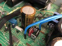
Mod no 1. C909, C910 and C923 changed to new ones
For those specific parts I chose Samwha HE series, two 10000uF (an upgrade from 8200uF) and 4700 uF accordingly. My decision was dictated by cost, availability and spec (ripple current, ESR, dimensions). Fun fact, famous Orange Amplification puts Samwha caps in their 1800 GBP bass tube amps. Also my friend who works in the automation industry swears for them. They seem to be decent caps, despite bad reputation.
Original Nichicons were manufactured in 1990 and about 15-20% off. It was the time for them to go.
When I first listened to the amp with new main filter caps it sounded terrible! Lost all the bass and was predominated by harsh high-mids. Things got better after couple hours though, but I felt not much of a difference before and after caps replacement.
Also THD was showing me I was right. Maybe if I pushed the amp louder and hit a lower note during measurement the difference would be more visible.
Mod no. 2. Black Gates 10uF/50V preamp coupling electrolytes to WIMA MKS 10uF/50V
I also replaced Elna RE2 470uF/25V from the IC regs to BCcomponents 136 KO 470uF/25V.
Oh boy! The amp started to sing, literally. Every aspect of the sound became much better, more real, transparent, clear, you name it. I suddenly felt great bass extension and punch, so much I turned off the tone circuit. Even though I keep tone knobs at noon, the baxandall circuit adds something at both ends of audio band.
I was extremely happy with the result but THD stayed unchanged (again, flawed setup could contribute)
Mod no. 3. The Op amp rolling.
I was happy with the sound but NE5532 is not the most regarded op amp out there.
I had an OPA2134 handy so I tried it out. Well, the sound stage became super wide and pointy although I could hear strange forwardness of some high register notes. Probably because of that some people state this chip is unveiling. In my book it's just overexaggeration. Dynamics were improved, which was very appealing, but in the same time bass notes were less pronounced, less textured. The sound also lost some of the resolution (at least in unchanged Rotel's circuit). And that's a big no no for me. I could hear were the singer is exactly in the mix, but the voice was a little grainy, smeared.
I hopped into the datasheet and something caught my eye. The THD+N of this chip rises sharply from 1kHz and up. Maybe that's the cause of that high register forwardness.
It was not the chip for me. No doubt Rotel's layout isn't optimal for fast op amps, therefore some of the negatives may be related to this fact.
Unfortunately I didn't take a shot of RTA screen but at that time I still didn't figure out the ground loop problem, so not a big loss.
I also had a LM4562 but a +/- 19.3V rails ware a little too high for it (17V maximum). I figured all it takes to alter regulators output is to change zener diodes D901/D902. I put 16V in place of 18V parts and voila, I had 17V rails.
Before changing the chip I wanted to measure and listen to the stock NE5532 at lower supply voltage.

The sound lost some of the attack, excitement and sparkle but overall it was OK.
Then I swapped the IC to LM4562. Soundwise, it was quite similar to NE5532 run on lower voltage, although details were again smeared. It acted like the OPA2134 in that regard.

Notice how much more noise there in the sub 900Hz area. Also harmonic content looks much worse.
Than I swapped again to NE5532 and set regs to 22V. Didn't listen to it yet but saved a plot. Such high voltage puts a strain on regulator and decoupling caps.

As you can see the harmonics interrelation has changed (compare 2nd and 4th plot). Same chip and everything else, different supply voltage (and perhaps current?).
I really love how the old Signetics NE5532 performs in this amp. It seems like designers knew how to make it sound great, without fancy regulators and great PCB layout. It has all it takes to give me chills during listening sessions.
And thus its THD spec is a not so impressive 0.3%, so there is a long way down to the 0.003% that I get consistently in the upgraded RA-931's. But I am interested in hearing your ideas.
The operating manual states THD should be no more than 0.3% at 8 ohms load, full power, 20-20k Hz and less than 0.1% at half power. At 10W 1k Hz I measured about 0.033% and that was before I resolved a ground loop issue with my PC.
Ignore terrible THD+N. These amps are actually much better than the spec suggest.
Mod no 1. C909, C910 and C923 changed to new ones
For those specific parts I chose Samwha HE series, two 10000uF (an upgrade from 8200uF) and 4700 uF accordingly. My decision was dictated by cost, availability and spec (ripple current, ESR, dimensions). Fun fact, famous Orange Amplification puts Samwha caps in their 1800 GBP bass tube amps. Also my friend who works in the automation industry swears for them. They seem to be decent caps, despite bad reputation.
Original Nichicons were manufactured in 1990 and about 15-20% off. It was the time for them to go.
When I first listened to the amp with new main filter caps it sounded terrible! Lost all the bass and was predominated by harsh high-mids. Things got better after couple hours though, but I felt not much of a difference before and after caps replacement.
Also THD was showing me I was right. Maybe if I pushed the amp louder and hit a lower note during measurement the difference would be more visible.
Mod no. 2. Black Gates 10uF/50V preamp coupling electrolytes to WIMA MKS 10uF/50V
I also replaced Elna RE2 470uF/25V from the IC regs to BCcomponents 136 KO 470uF/25V.
Oh boy! The amp started to sing, literally. Every aspect of the sound became much better, more real, transparent, clear, you name it. I suddenly felt great bass extension and punch, so much I turned off the tone circuit. Even though I keep tone knobs at noon, the baxandall circuit adds something at both ends of audio band.
I was extremely happy with the result but THD stayed unchanged (again, flawed setup could contribute)
Mod no. 3. The Op amp rolling.
I was happy with the sound but NE5532 is not the most regarded op amp out there.
I had an OPA2134 handy so I tried it out. Well, the sound stage became super wide and pointy although I could hear strange forwardness of some high register notes. Probably because of that some people state this chip is unveiling. In my book it's just overexaggeration. Dynamics were improved, which was very appealing, but in the same time bass notes were less pronounced, less textured. The sound also lost some of the resolution (at least in unchanged Rotel's circuit). And that's a big no no for me. I could hear were the singer is exactly in the mix, but the voice was a little grainy, smeared.
I hopped into the datasheet and something caught my eye. The THD+N of this chip rises sharply from 1kHz and up. Maybe that's the cause of that high register forwardness.
It was not the chip for me. No doubt Rotel's layout isn't optimal for fast op amps, therefore some of the negatives may be related to this fact.
Unfortunately I didn't take a shot of RTA screen but at that time I still didn't figure out the ground loop problem, so not a big loss.
I also had a LM4562 but a +/- 19.3V rails ware a little too high for it (17V maximum). I figured all it takes to alter regulators output is to change zener diodes D901/D902. I put 16V in place of 18V parts and voila, I had 17V rails.
Before changing the chip I wanted to measure and listen to the stock NE5532 at lower supply voltage.
The sound lost some of the attack, excitement and sparkle but overall it was OK.
Then I swapped the IC to LM4562. Soundwise, it was quite similar to NE5532 run on lower voltage, although details were again smeared. It acted like the OPA2134 in that regard.
Notice how much more noise there in the sub 900Hz area. Also harmonic content looks much worse.
Than I swapped again to NE5532 and set regs to 22V. Didn't listen to it yet but saved a plot. Such high voltage puts a strain on regulator and decoupling caps.
As you can see the harmonics interrelation has changed (compare 2nd and 4th plot). Same chip and everything else, different supply voltage (and perhaps current?).
I really love how the old Signetics NE5532 performs in this amp. It seems like designers knew how to make it sound great, without fancy regulators and great PCB layout. It has all it takes to give me chills during listening sessions.
I almost forgot your question:
That is actually a very good question that has - and probably will be debated for a long time.
It's a bit OT and with the risk of starting a discussion frenzy let me start with the old dispute:
"If you listen to say, a steady kick drum beat, you'd expect the sound wave pulses coming towards you to be as if you sat in front of the drum set on stage.
So the speaker membrane should "push" towards you - right?.
The problem comes e.g. when the speakers have tuned bass reflex ports - or are back loaded horns.
The speaker membrane's "push" movement outwards will cause a stronger inverted "pull" in either the tuned port or horn mouth. So should the amp then invert the signal?
But when you have in-wall speakers, sealed boxes or just put on headphones it is the other way round. So should the amp then be non-inverting?
And - does it really matter?"
Either way, as a much younger man I played in a rock band and for some reason was always placed right next to the drummer.
I know his crash cymbal accounts for my tinnitus and the PA system monitors for my rattled brain cells. But did his kick drum push or pull?
You could say that after I stopped playing live, I sort of phased that question out. Pardon the pun.")
Does it matter what's the phase of a signal that feeds the power amp?That is actually a very good question that has - and probably will be debated for a long time.
It's a bit OT and with the risk of starting a discussion frenzy let me start with the old dispute:
"If you listen to say, a steady kick drum beat, you'd expect the sound wave pulses coming towards you to be as if you sat in front of the drum set on stage.
So the speaker membrane should "push" towards you - right?.
The problem comes e.g. when the speakers have tuned bass reflex ports - or are back loaded horns.
The speaker membrane's "push" movement outwards will cause a stronger inverted "pull" in either the tuned port or horn mouth. So should the amp then invert the signal?
But when you have in-wall speakers, sealed boxes or just put on headphones it is the other way round. So should the amp then be non-inverting?
And - does it really matter?"
Either way, as a much younger man I played in a rock band and for some reason was always placed right next to the drummer.
I know his crash cymbal accounts for my tinnitus and the PA system monitors for my rattled brain cells. But did his kick drum push or pull?
You could say that after I stopped playing live, I sort of phased that question out. Pardon the pun.
I am dum! I remeasured ripple voltage and it turns out I didn't convert peak-to-peak to rms
Well, ripple voltage actually is as follows:
preamp: 1.77mV (noise)
power amp input - positive: 19.8 mV
power amp input - negative: 10.6 mV
positive and negative rail: 124 mV
The headphone output pickup point is an obvious error...
Yes, it's tapped from speaker output terminals, so just after the fuse on the schematic. Wires from there go to remote speakers switch and phone output board.
BTW. there are lots of unused holes for caps and resistors, at every terminal that goes to the rear panel, also for zobel network.
What I can confirm is that just by increasing the filtering capacitors to 10,000uF/50V in all 3 positions, the ripple is reduced to 70mV on the output stage rails, and 7mV on the input stage rails.
Which amp exactly do you own Extreme_Boky? I don't think I'll ever achieve 70mV on main rails in my 840BX4. I already have new 10000uF main caps. Bias is a touch hotter, 3mV at test points instead of 2.5.
Last edited:
I have 820BX4, same as 840BX4 (840 has tone controls)
I bought one off eBay just for fun... and fun I had indeed!
It sounds absolutely brilliant, but I modified the living thing out of it... again, just for fun.
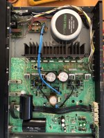
I will try to list everything I did to it:
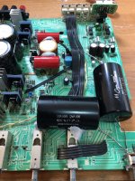
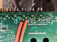
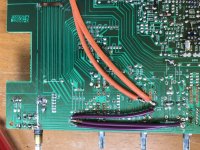
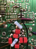
1. The mains transformer was wired for 240V, I live in a country that uses 240V mains. So, to increase the DC rails (from around 32V initially), I wired the 220V transformer primary tap to 240V mains. Now I have DC rails sitting at 36V DC. The output power at the onset of clipping @ 6 ohms is 84W (!!!). The amp keeps this power across the full audio spectrum, which is an outstanding result.
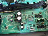
2. The TAPE IN input is routed via least amount of input switching, so I used this input to do one of my favourite mods - cut the tracks to remove inductance/impedance caused by the PCB, and wire everything point-to-point, using a combination of pure silver and pure copper ribbon cables. The unused, floating PCB tracks (all of them - those ones that came floating from the factory because there's no tone controls) are brought to a ground potential.
3. The sound coupling capacitors (I think they were BlackGates 10uF) are now Mundorf silver-in-oil. I know, an overkill, but I am not using them any more because I like AuriCaps XO better... so I had a spare pair of Mundorfs I pulled out from another amp
4. The bridge rectifier, and the two diodes that are used to create B+ for the pre-amp section, are now all discrete fast switching/soft recovery diodes, dampened by 0.01uF WIMA MKPs.
5. The remaining 0.1uF decoupling caps (used to be film types, a total of 8) are now SMD devices
6. The pick-up point for the negative feedback is now right at the speaker binding posts (at the correct point, i.e. at the amplifier output)
7. The voltage regulators for MM/MC stage is decoupled by my favourite combo: Panasonic SEPF / Elna Silmic II. It sounds really good and is dead-quiet.
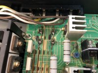
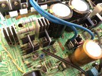
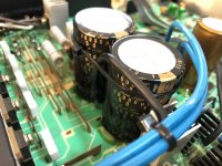
8. The current mirror / pre-VAS & VAS transistors have received little heatsinks. They were running so hot that the PCB underneath has almost burnt.
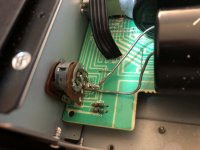
9. The volume pot wiper is connected straight to Mundorfs (no PCB tracks)
10. The other side of Mundorfs goes straight to the IN of the amplifier (again, no PCB tracks)
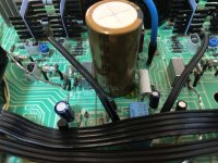
11. DC and B+ filtering caps are now Nichicons
12. The fuses in series with the speaker outputs are now gone...
13. The B+ voltage rail to the pre-amp section is now wired via Panasonic 0.47ohm 3W resistors, point-to-point.
14. Ground uniformity improvements are done across the whole PCB
15. The headphone wiring goes straight to the jack, the speaker "remote" switch is not in use any more, all pins brought to ground potential.
16. The bypass caps, across Nichicons, are BlackGate NX types, 0.1uF (20 bucks a pop on eBay, NOS...!!!)
...and one that could be of real importance to everyone who complained about "weak bass"...
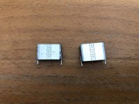
...17. The truly terrible sound-coupling feedback milar 2.2uF caps are now nice film types: Audiophyler Mundorfs. This brings life back, bass definition... simply beautiful. I actually soldered nice short silver ribbons to the PCB, and will play with capacitors' type and value to fine-tune the sound.... maybe... because the amp sounds already bloody marvellous with Audiophylers.
Sound..?? Drives the hell out of my Dynaudios with a very natural presentation, wide soundstage, beautifull highs. Very very nice.
I bought one off eBay just for fun... and fun I had indeed!
It sounds absolutely brilliant, but I modified the living thing out of it... again, just for fun.
I will try to list everything I did to it:
1. The mains transformer was wired for 240V, I live in a country that uses 240V mains. So, to increase the DC rails (from around 32V initially), I wired the 220V transformer primary tap to 240V mains. Now I have DC rails sitting at 36V DC. The output power at the onset of clipping @ 6 ohms is 84W (!!!). The amp keeps this power across the full audio spectrum, which is an outstanding result.
2. The TAPE IN input is routed via least amount of input switching, so I used this input to do one of my favourite mods - cut the tracks to remove inductance/impedance caused by the PCB, and wire everything point-to-point, using a combination of pure silver and pure copper ribbon cables. The unused, floating PCB tracks (all of them - those ones that came floating from the factory because there's no tone controls) are brought to a ground potential.
3. The sound coupling capacitors (I think they were BlackGates 10uF) are now Mundorf silver-in-oil. I know, an overkill, but I am not using them any more because I like AuriCaps XO better... so I had a spare pair of Mundorfs I pulled out from another amp
4. The bridge rectifier, and the two diodes that are used to create B+ for the pre-amp section, are now all discrete fast switching/soft recovery diodes, dampened by 0.01uF WIMA MKPs.
5. The remaining 0.1uF decoupling caps (used to be film types, a total of 8) are now SMD devices
6. The pick-up point for the negative feedback is now right at the speaker binding posts (at the correct point, i.e. at the amplifier output)
7. The voltage regulators for MM/MC stage is decoupled by my favourite combo: Panasonic SEPF / Elna Silmic II. It sounds really good and is dead-quiet.
8. The current mirror / pre-VAS & VAS transistors have received little heatsinks. They were running so hot that the PCB underneath has almost burnt.
9. The volume pot wiper is connected straight to Mundorfs (no PCB tracks)
10. The other side of Mundorfs goes straight to the IN of the amplifier (again, no PCB tracks)
11. DC and B+ filtering caps are now Nichicons
12. The fuses in series with the speaker outputs are now gone...
13. The B+ voltage rail to the pre-amp section is now wired via Panasonic 0.47ohm 3W resistors, point-to-point.
14. Ground uniformity improvements are done across the whole PCB
15. The headphone wiring goes straight to the jack, the speaker "remote" switch is not in use any more, all pins brought to ground potential.
16. The bypass caps, across Nichicons, are BlackGate NX types, 0.1uF (20 bucks a pop on eBay, NOS...!!!)
...and one that could be of real importance to everyone who complained about "weak bass"...
...17. The truly terrible sound-coupling feedback milar 2.2uF caps are now nice film types: Audiophyler Mundorfs. This brings life back, bass definition... simply beautiful. I actually soldered nice short silver ribbons to the PCB, and will play with capacitors' type and value to fine-tune the sound.... maybe... because the amp sounds already bloody marvellous with Audiophylers.
Sound..?? Drives the hell out of my Dynaudios with a very natural presentation, wide soundstage, beautifull highs. Very very nice.
Attachments
Last edited:
... more photos
Attachments

Last edited:
Now I'm curious how 840bx4 sounds with a bypassed preamp I can see the 820bx4, apart from the phono stage, has no preamp at all! Or it has a passive one, if you will. Some say the best opamp is no opamp I guess in such scenario the amplifier is more sensitive to source impedance and capacitance (interconnects!). Especially with a DAC like mine, in which after the DA chip I have transformers instead of a more standard solid state stage.
It seems like your amp has a different power transformer. The part number is different, also rail voltage is higher in 840bx4 of mine. I have 43VDC on a 220VAC tap and 230VAC mains. It may solve the mystery of higher ripple voltage in my unit.
4. The bridge rectifier, and the two diodes that are used to create B+ for the pre-amp section, are now all discrete fast switching/soft recovery diodes, dampened by 0.01uF WIMA MKPs.
Do you have any FFT plots before and after? How do you feel about this mod? Can you hear a difference? Why MKP instead of ceramics?
5. The remaining 0.1uF decoupling caps (used to be film types, a total of 8) are now SMD devices
Ceramics? What type? What's your opinion on this?
12. The fuses in series with the speaker outputs are now gone...
I did this as well a couple of years ago, it was my first modification and I never looked back. The improvement is significant, at least in my system. A fuse in audio signal path is bad, especially if it's outside the feedback loop!
17. The truly terrible sound-coupling feedback milar 2.2uF caps are now nice film types: Audiophyler Mundorfs. This brings life back, bass definition... simply beautiful. I actually soldered nice short silver ribbons to the PCB, and will play with capacitors' type and value to fine-tune the sound.... maybe... because the amp sounds already bloody marvellous with Audiophylers.
Wow, this is truly interesting. I felt the same difference when I bypassed output fuses. And then after switching from electrolytic coupling caps to polyester Wimas. Since this feedback cap is already a polyester, I'd never thought a polyprypelyne can improve things in such dramatic way.
I can see the 820bx4, apart from the phono stage, has no preamp at all! Or it has a passive one, if you will. Some say the best opamp is no opamp I guess in such scenario the amplifier is more sensitive to source impedance and capacitance (interconnects!). Especially with a DAC like mine, in which after the DA chip I have transformers instead of a more standard solid state stage. It seems like your amp has a different power transformer. The part number is different, also rail voltage is higher in 840bx4 of mine. I have 43VDC on a 220VAC tap and 230VAC mains. It may solve the mystery of higher ripple voltage in my unit.
4. The bridge rectifier, and the two diodes that are used to create B+ for the pre-amp section, are now all discrete fast switching/soft recovery diodes, dampened by 0.01uF WIMA MKPs.
Do you have any FFT plots before and after? How do you feel about this mod? Can you hear a difference? Why MKP instead of ceramics?
5. The remaining 0.1uF decoupling caps (used to be film types, a total of 8) are now SMD devices
Ceramics? What type? What's your opinion on this?
12. The fuses in series with the speaker outputs are now gone...
I did this as well a couple of years ago, it was my first modification and I never looked back. The improvement is significant, at least in my system. A fuse in audio signal path is bad, especially if it's outside the feedback loop!
17. The truly terrible sound-coupling feedback milar 2.2uF caps are now nice film types: Audiophyler Mundorfs. This brings life back, bass definition... simply beautiful. I actually soldered nice short silver ribbons to the PCB, and will play with capacitors' type and value to fine-tune the sound.... maybe... because the amp sounds already bloody marvellous with Audiophylers.
Wow, this is truly interesting. I felt the same difference when I bypassed output fuses. And then after switching from electrolytic coupling caps to polyester Wimas. Since this feedback cap is already a polyester, I'd never thought a polyprypelyne can improve things in such dramatic way.
The latest ripple figures are 5mV on pre-amp rails (a drop from 7mV... I "blame" the 0.47ohm / 3W resistors for this), 70mV (no change) on main amplifier rails.
The fast switching/soft recovery diodes is a routine mod I do... I did mods in stages, this being one of them. The sound was more relaxed, better flowing, more space and better high extension. The WIMA's are not necessary, but I do like what they do to the sound, in combination with no PCB tracks' inductance/capacitance on TAPE IN, and silver ribbons used instead. Also, the Nichicons are quite revealing (bright?). No plots.
0.1uF / 100V MLC capacitors, P/N: 80-C1812C104J1G... there are not many NPO (COG) caps in such high value (0.1uF), but this is one of them!!!... a great sounding cap. The story here is... the original green polyester caps were replaced with WIMA 0.1uF / 250V MKP's but I did not like the sound... too soft and no extension. So, I went all the way to the other end and used MLC's - COG. Excellent result, very quiet background and great extension/speed. Might be too much... but this depends on the rest of the system and personal preferences.
The mylar 2.2uF / 100V is where you can tune the sound to your liking, "externally", without too much hassle... Install little wires and keep playing with different capacitor types until you find one that you like / that blends nicely with the rest of your system.
I forgot to mention - I also removed the MONO-STEREO switch from the signal path altogether
), 70mV (no change) on main amplifier rails.The fast switching/soft recovery diodes is a routine mod I do... I did mods in stages, this being one of them. The sound was more relaxed, better flowing, more space and better high extension. The WIMA's are not necessary, but I do like what they do to the sound, in combination with no PCB tracks' inductance/capacitance on TAPE IN, and silver ribbons used instead. Also, the Nichicons are quite revealing (bright?). No plots.
0.1uF / 100V MLC capacitors, P/N: 80-C1812C104J1G... there are not many NPO (COG) caps in such high value (0.1uF), but this is one of them!!!... a great sounding cap. The story here is... the original green polyester caps were replaced with WIMA 0.1uF / 250V MKP's but I did not like the sound... too soft and no extension. So, I went all the way to the other end and used MLC's - COG. Excellent result, very quiet background and great extension/speed. Might be too much... but this depends on the rest of the system and personal preferences.
The mylar 2.2uF / 100V is where you can tune the sound to your liking, "externally", without too much hassle... Install little wires and keep playing with different capacitor types until you find one that you like / that blends nicely with the rest of your system.
I forgot to mention - I also removed the MONO-STEREO switch from the signal path altogether
- Home
- Amplifiers
- Solid State
- Improve a Rotel amp THD by 20dB!