This I think is where commercial constraints come into play, things such as heatsink size and PSU capacity.
18ma is way below an optimum sort of value for this type of stage. If you read the work done by Doug Self back in the 1990's it was found that specific values of quiescent current for specific emitter value resistor values seemed to give the best thd performance. For this configuration of output stage you are looking at around 105 milliamps give or take as somewhere in the optimal range.
One problem with the Rotel (as you discovered) is the poor shared grounding. Increasing the quiescent current increase the ripple voltage at idle which makes the perceived hum and noise much worse.
Indeed. But my aim was to improve an old existing amp with minimal cosmetic changes and on a budget. Raising the Iq to over 100mA would produce somewhere up to 10W (?) on the small internal heatsink in the Rotel - and that is even before the band begins to play hot stuff.
 Larger heatsinks, fans, etc. were not on the cards.
Having said that, I do usually set the bias a bit higher than as per the manual in a feeble attempt to stay more class A than B at WAF listening levels - with due checks that the HS is still touchable under idle conditions.
Wouldn't you agree that perhaps more could be achieved by less by optimising the VAS compensation?
Wouldn't you agree that perhaps more could be achieved by less by optimising the VAS compensation?
Possibly... but its like that for a reason.
Its a long while ago now that I modded and played around with my old Rotel but I did add output inductors. Maybe I wasn't happy with it under light capacitive loading after the FET mod... but its all a long time ago and I can't remember all the finer points now.
It is what it is... a true budget classic of the era... but how far you can take it, well I wouldn't like to say.
Indeed. But my aim was to improve an old existing amp with minimal cosmetic changes and on a budget. Raising the Iq to over 100mA would produce somewhere up to 10W (?) on the small internal heatsink in the Rotel - and that is even before the band begins to play hot stuff.
Having said that, I do usually set the bias a bit higher than as per the manual in a feeble attempt to stay more class A than B at WAF listening levels - with due checks that the HS is still touchable under idle conditions.
Wouldn't you agree that perhaps more could be achieved by less by optimising the VAS compensation?
This "fix" has already been suggested. Bob Cordell wrote some papers in 1980 that may give you some pointers see CordellAudio.com - Another View of TIM
Ok, finally got back to the Rotel RA-820AX project.
I now seem to have tamed the RTA front-end asus U7 by building it into an old prototype amp box together with the 8ohm dummy load power resistors, reducing the cable clutter. (So much for a pretty “external” USB audio device!)
Anyway, I can now analyze the elusive 50Hz noise on the RTA spectra, because:
Loopback signal inside the new dummy load box - clean.
Loopback signal with cables outside that box - clean.
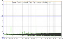
Loopback signal through Rotel 820AX tape out – hey presto loads of 50Hz and odd harmonics plus a second harmonic 2kHz - even with the amp power OFF (see Fig 1)! The tape-out tracks have two 1K series protection resistors which apparently act as antenna/resonator circuits of its own? Also I suspect that the U7 uses very high input impedance mosfet circuitry?
Sensitivity is a good thing until something bites you in the back.
So, I devised a different way of routing a signal through the “pre- pre-amp” tracks of the amp:
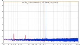
Sending the test signal through the Left CD input, switching the tone control to mono – and picking up through the Right CD in(now out)put. That way it would go through all tracks, jumpers and switches and only be loaded by the volume and balance pots and preamp input components. Now:
Loopback signal with amp power OFF – clean (blue in fig 2)
Loopback signal with amp power ON – some (-100dB) 50Hz (red in fig 2)
This 50Hz signal would of course be duly amplified by the active amp circuits and could possibly explain the previous RTA results? In which case this root cause should be eliminated - or reduced.
I guess that a proper double sided PCB with a good ground plane would solve much of this problem? But, as this is not feasible, any suggestions for any obvious points of attack from you guys?
I now seem to have tamed the RTA front-end asus U7 by building it into an old prototype amp box together with the 8ohm dummy load power resistors, reducing the cable clutter. (So much for a pretty “external” USB audio device!)
Anyway, I can now analyze the elusive 50Hz noise on the RTA spectra, because:
Loopback signal inside the new dummy load box - clean.
Loopback signal with cables outside that box - clean.
Loopback signal through Rotel 820AX tape out – hey presto loads of 50Hz and odd harmonics plus a second harmonic 2kHz - even with the amp power OFF (see Fig 1)! The tape-out tracks have two 1K series protection resistors which apparently act as antenna/resonator circuits of its own? Also I suspect that the U7 uses very high input impedance mosfet circuitry?
Sensitivity is a good thing until something bites you in the back.
So, I devised a different way of routing a signal through the “pre- pre-amp” tracks of the amp:
Sending the test signal through the Left CD input, switching the tone control to mono – and picking up through the Right CD in(now out)put. That way it would go through all tracks, jumpers and switches and only be loaded by the volume and balance pots and preamp input components. Now:
Loopback signal with amp power OFF – clean (blue in fig 2)
Loopback signal with amp power ON – some (-100dB) 50Hz (red in fig 2)
This 50Hz signal would of course be duly amplified by the active amp circuits and could possibly explain the previous RTA results? In which case this root cause should be eliminated - or reduced.
I guess that a proper double sided PCB with a good ground plane would solve much of this problem? But, as this is not feasible, any suggestions for any obvious points of attack from you guys?
Attachments
Hi AngelP,
Nice work. Now you have found out first hand how much trouble it can be to make a "simple" measurement.
I would test the way you would normally test. L channel in, L channel out. Same for the right channel. That way you can perform crosstalk tests as well.
Did you connect the case to the computer sound card common, or the DUT case? Try both and go with the lower noise option.
-Chris
Hi AngelP,
Nice work. Now you have found out first hand how much trouble it can be to make a "simple" measurement.
I would test the way you would normally test. L channel in, L channel out. Same for the right channel. That way you can perform crosstalk tests as well.
Did you connect the case to the computer sound card common, or the DUT case? Try both and go with the lower noise option.
-Chris
Hi Chris,
Yes, nothing is simple when you are diving below -100dB on a shoestring budget scuba equipment.
The sound card common is connected to the amp DUT's common. Grounding the box which it sits in did not change anything. Apparently it performs as a simple Faraday's cage, helping the insufficient shielding of the ASUS Xonar U7 box.
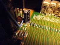
As per your suggestion, I reverted to the L_in – L_tape out and tried all sorts of grounding and shielding of the input circuitry to reduce the 50Hz noise – no luck. I finally found that the culprits were indeed the 1K tape out series resistors. Firstly, they were physically placed only a few mm away from one of the IC power supply input ripple capacitors (Fig 1) – although relocating them to a more “quiet” part of the PCB did actually not improve things that much.
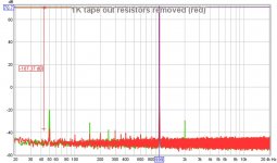
However, simply shorting them did (Fig 2), also note that the strange green 2kHz peak is gone. Apparently, the 1K's were picking up the eddy currents from the transformer to the 820AX's casing as the 50Hz peak actually dropped when I removed the top cover. Now, due to the design of the 820AX there are no easy ways to break or isolate these eddy loops – nor can you easily rotate or move the mains transformer.
So, unless someone comes up with a great new idea, I guess that we are stuck with what we got.
And anyway, an old amp with all input circuitry noise peaks now below -108dB is not to be sneezed at?
How or whether this improvement will affect the amp's total output THD is – next.
Attachments
Hi AngelP,
Try to mount the transformer on a sub-chassis, then you might be able to drill holes that match the transformer direction for lower hum pick up. Also, now the eddy currents will flow in your sub-chassis and not the main chassis.
For the route of the track, take a strip of copper and mount it on edge along that first grounding trace. Just tack solder the edge of that strip every so often. That might help lower noise pickup along that route. Don't ground the far end of the strip to your audio ground. Try it open and also to the chassis with a short thick wire.
This should be an interesting experiment for you. There are always options.")
-Chris
Try to mount the transformer on a sub-chassis, then you might be able to drill holes that match the transformer direction for lower hum pick up. Also, now the eddy currents will flow in your sub-chassis and not the main chassis.
For the route of the track, take a strip of copper and mount it on edge along that first grounding trace. Just tack solder the edge of that strip every so often. That might help lower noise pickup along that route. Don't ground the far end of the strip to your audio ground. Try it open and also to the chassis with a short thick wire.
This should be an interesting experiment for you. There are always options.
-Chris
Well, shorting the tape-out resistors did not change much in the overall THD. Which is perhaps not unexpected because if these 1k resistors could pick up intra-casing noise so could most other input circuitry components. So, it seems to be merely tinkering at the edges without any real bang for the buck.
Anyway, thank you Chris for your good suggestions, but they are not easily done due to space and cabling issues.
So instead of ripping out the 820's transformer to double case or rotate it, I first employed an open RA-931 I had on the bench from which I could connect (steal) external +/-27V AC power into the RA-820AX.
Another good try, but that also gave no real change in the noise spectrum.
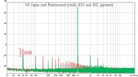
Then, I connected the +/- 37V DC from the 931 and bingo! (see attached fig.) Low frequency noise significantly down and in particular the 50Hz and odd harmonics. As the ripple on the 931 DC was as bad as anything, the main noise culprit must therefore be the RA-820AX's proudly towering bridge rectifier and/or its smoothing caps?
I feel a Graetz bridge and cap mod coming up Stay tuned.
Anyway, thank you Chris for your good suggestions, but they are not easily done due to space and cabling issues.
So instead of ripping out the 820's transformer to double case or rotate it, I first employed an open RA-931 I had on the bench from which I could connect (steal) external +/-27V AC power into the RA-820AX.
Another good try, but that also gave no real change in the noise spectrum.
Then, I connected the +/- 37V DC from the 931 and bingo! (see attached fig.) Low frequency noise significantly down and in particular the 50Hz and odd harmonics. As the ripple on the 931 DC was as bad as anything, the main noise culprit must therefore be the RA-820AX's proudly towering bridge rectifier and/or its smoothing caps?
I feel a Graetz bridge and cap mod coming up
Stay tuned.Attachments
Last edited:
Hi AngelP,
I didn't say they would be easy changes, but simply a suggestion that you may or may not be interested in following. I think your experiments with another DC source were very effective. Good thinking on your part! I would be interested to see what you come up with.
Do you have the foil diagram for this unit in the power supply area? I'm wondering if it isn't the current spikes between the capacitors, transformer and rectifiers. The traces might be the problem if current spikes are permitted to share a trace with normal common connections. This would have been solved when you used the external power supply as well. I wish you good hunting and great success!
-Chris
Been looking at this thread trying to read as much is possible, i would say that it is admirable work even though my personal opinion is different .
Simplify things for a minute , take a brake and a cup of coffee even beer if you like and scroll behind your mind all the comments you have been reading about circuits in the forum regarding relatively far simpler circuits like the DX amplifier , or the P3A or first watt circuits or even the ZCA ( zero component amplifier ) By our friend Mark Houston
You will find descriptions and listening impressions that could actually fit to amplifiers tagged with 5-6 digit numbers Wonder why ?
I can explain ...its because these circuits and the DIY implementations are very very simple We have people that spent like 3000 USD for a DX amplifier over designing almost everything and included in a fancy enclosure ,But obviously those play well not because are over designed but because these are so simple .
So class Ab amplifiers if you manage to solve the electronic issues either those coming from design mistakes or cost cuts the next thing you need to solve is structure and topology mistakes and arrangements ...The problem though in your case in a given enclosure and structure it cannot be done ...
Redesign the PCB under specific rules of any of the known amplifiers , built and design a proper psu next to it also designed under specific rules , built the peripherals that you need designed also under the specific rules and your spectrum analyzer will jump like a kangaroo from pleasure ....
If you are able to measure or listen the difference in a Denon amplifier ( for example ) that has 4X10.000 ufd located 3cm away from the outputs next to a Yamaha that has 2x22.000uf but located next to the trafo and hardwired to the output board then you are ready for such a project ...
Please notice that the capacitor thing is just one example there is about 15-20 more rules to keep in order to make your spectrum analyzer happy !!!
Kind regards and thank you for sharing your work
Sakis
Hi Sakis,
Well, AngelP is trying to solve a specific problem, and is also investigating the work in general. That is a worthwhile undertaking. To learn those rules.
How would you compare Denon and Yamaha these days Sakis? I haven't bothered to listen since they went surround.
-Chris
Well, AngelP is trying to solve a specific problem, and is also investigating the work in general. That is a worthwhile undertaking. To learn those rules.
I did that for years and years. The Yamaha sounds "thinner" if that is a valid description. They also made some models that would burn out all by themselves without warning. Then there was the Zero Distortion Rule (ZDR) amplifiers that would cook the ZDR transformer almost every time. By comparison, Denon product was tougher to kill. They sounded differently, and looked different on instruments. There is much more going on than the capacitors and how they are connected to the circuits.If you are able to measure or listen the difference in a Denon amplifier ( for example ) that has 4X10.000 ufd located 3cm away from the outputs next to a Yamaha that has 2x22.000uf but located next to the trafo and hardwired to the output board then you are ready for such a project ...
How would you compare Denon and Yamaha these days Sakis? I haven't bothered to listen since they went surround.
-Chris
well now days Chris both Yamaha and Denon are ...hand made in China... expect no innovation in the audio section in general circuits that we have seen in the past , while parts are getting cheaper and cheaper .
In between input is getting loaded with non audio related things like USB , firewire , LAn , and chan and ban and kan ...resulting way too many processors ...
Failure is related to component problems , audio amplifiers are way overestimated and processors get to control the amps in order to keep them safe ....
In my vocation time in august i might create a list with model and description
It is 5 years now that we have an electronics data base for everything which is probably loaded with everything like descriptions of failure and repair procedures
that will probably include more or less 5000 devices ...
i am not sure how to extract those data but i will try !!!
I'm going to ask a stupid question - what effect did this mod actually have on the overall sound of the amp - ie - what actually changed... audibly?
I ask because I've never done an A/B comparison between two versions of the same topology where one simply had a lower noise floor. Was the difference night and day or was it very subtle?
I'd be dead keen to hear your impressions on what actually "changed" in the sound as, so far, you've only been speaking about test tones.
I'm going to ask a stupid question - what effect did this mod actually have on the overall sound of the amp - ie - what actually changed... audibly?
I ask because I've never done an A/B comparison between two versions of the same topology where one simply had a lower noise floor. Was the difference night and day or was it very subtle?
I'd be dead keen to hear your impressions on what actually "changed" in the sound as, so far, you've only been speaking about test tones.
That is not a dumb question, in fact it is - or should be the main reason why we bother with all this.
Firstly, I am no fan of – and I am absolutely no expert in audiophile press linguistic gibberish.
But that said, I do accept that our ears can definitely register nuances that we can't or don't measure – particularly audible in comparative tests. And that we also need some way of describing what our golden ears “measure”. So after the first three mods - here goes:
Not having a second stock RA-820AX around, we first A/B tested it against an RA-931mkII. The most immediate impression was that the modded 820AX's bass and dynamics were indeed firmer, musical detail and clarity was better – yet it still sounded pleasantly as a Rotel amp. As one on the listening team coined it: “Round as a Rotel – but much firmer and without the hum”.
Then we set it up against a Hiraga “Le Monstre” class A amp, and while perhaps that is not quite fair, the 820AX detail was actually not that far off. Actually, it held its own pretty well.
But, before getting carried away into ecstatic rants of “Giant Slayer” or “Magic Monster Mod” …..eh, I guess that I'll just leave my audiophile journalistic dentures by the door as I sneak back into the lab.
However, I have listened to the 820AX in my main system setup between each stage of the mods and measurements - and to my ears the major audible improvement perhaps came in stage 2 – the input stage filter and cascode transistor mod. But, of course I can't quantify that in any way.
Cheers,
Per
Well, as I see it you've got everything you need for an A/B comparison. Take a mono signal, split it into each of the inputs of your modded and unmodded channels, up the gain and then walk back and forth between the two speakers.
If there's a remarkable difference in the mids and highs, you'll hear it. The bass will be more tricky so you could, in theory, check that by putting a momentary switch between your amp and your speaker and simply turning them on/off to do your comparison. So maybe putting the speakers next to each other and taking turns interrupting each of them and then listening to them together. Just a thought.
I've always struggled with this in the hifi world. So many opinions and virtually none of them are based on hard science. One person will tell you that the diff between 0.03 and 0.003% THD is inaudible. Others will tell you that your above impressions are nothing but placebo and some will be down right ignorant about it (telling you that you're an idiot for even suggesting that such a difference could exist).
In the end, I have little-to-no respect for the closed mindedness of the "pure" scientists because they generally deliver their opinions with disdain and an inability to admit that they might be wrong while the gold ears believers never offer anything more than... well.. they never offer anything other than their opinion.
And I've seen very few real articles out there that really talk about what's going on under the numbers. Like how much of a difference that 97% improvement is really going to make. And if the changes that you made are going to impact the "weight" of the sound simply because you put more capacitance in there for reserves, rather than the overall reduction in the THD.
I guess the problem is that I understand at least some of the math but I've not experimented enough (who has the time anymore) and I've not read enough white papers/articles on this sort of thing so I'm left wondering who... or even what... to believe.
Last edited:
Well, as I see it you've got everything you need for an A/B comparison. Take a mono signal, split it into each of the inputs of your modded and unmodded channels, up the gain and then walk back and forth between the two speakers.
If there's a remarkable difference in the mids and highs, you'll hear it. The bass will be more tricky so you could, in theory, check that by putting a momentary switch between your amp and your speaker and simply turning them on/off to do your comparison. So maybe putting the speakers next to each other and taking turns interrupting each of them and then listening to them together. Just a thought.
I've always struggled with this in the hifi world. So many opinions and virtually none of them are based on hard science. One person will tell you that the diff between 0.03 and 0.003% THD is inaudible. Others will tell you that your above impressions are nothing but placebo and some will be down right ignorant about it (telling you that you're an idiot for even suggesting that such a difference could exist).
In the end, I have little-to-no respect for the closed mindedness of the "pure" scientists because they generally deliver their opinions with disdain and an inability to admit that they might be wrong while the gold ears believers never offer anything more than... well.. they never offer anything other than their opinion.
And I've seen very few real articles out there that really talk about what's going on under the numbers. Like how much of a difference that 97% improvement is really going to make. And if the changes that you made are going to impact the "weight" of the sound simply because you put more capacitance in there for reserves, rather than the overall reduction in the THD.
I guess the problem is that I understand at least some of the math but I've not experimented enough (who has the time anymore) and I've not read enough white papers/articles on this sort of thing so I'm left wondering who... or even what... to believe.
I'm not sure that I quite understand all your points, but I'll try to answer.
Firstly, I could only keep the "one channel modded - other original" during mod stage 1. The later mods affects both channels.
Secondly, I think there is a general consensus that 0.03% THD is just audible (somebody please put me right or support that view).
In any case, the 100Hz hum was audible in the headphones. Would I be able to hear it from speakers several feet away - maybe not. Would my ears get used to it and start ignoring it? Probably.
But it should not be there. As you can see in the RTA traces, such noise produces a "carpet" of harmonic noise spikes far up in the part of the spectrum where our ears are most sensitive. Audible?
Well, my old uni professor in electro-acoustics had a memorable allegory:
"Having a noisy amp is like wading through a muddy stream. You sort of know the depth, but you are not really sure where or what the bottom is. A noise free amp is like wading through a clear mountain stream. Your feet will know every size, shape and even the colour of the pebbles and send chills up your spine. That could, of course, also be because of the cold water
"Secondly, I think there is a general consensus that 0.03% THD is just audible (somebody please put me right or support that view).
I might be measurable , but how could it be audible while combined with the loudspeakers many percent THD ?
On headphones ?
OS
I might be measurable , but how could it be audible while combined with the loudspeakers many percent THD ?
On headphones ?
OS
This wasn't the first time that I'd heard about the THD of speakers being much higher than that of an amp so I went looking and found this site:
Total Harmonic Distortion
Now, I don't think it's as simple as his test tone experiment suggests. He suggests that 1% distortion would be inaudible/indiscernible in music and I'm not sure that I'd agree - I think it will audibly change the overall tone of the signal rather than be easy to pick out but that's beside the point.
Either way, thanks for this thread - it's incented me to go out and learn a bit more about audio and, in general, distortion.
Hm... final thought. In retrospect, perhaps striving to achieve the 0.003% THD is worthwhile because everything in the signal path is going to add it's own distortion to the signal.
It's easy to say that the difference between 0.03 and 0.003 is inaudible, but when you start adding them all up (CD player, Pre/Pro/Amp, speakers and even the room) you are going to get 1-10% THD (most of which is going to be in the speakers and the room).
But there's no harm in minimizing the impact of any single component as it's only going to reduce the total THD. In fact, doing so means that you can focus your efforts on the other things that might be causing distortion.
THD is a pretty useless measure of distortion, at least it does not line up well with human perception at all, and that's been known since the 1930s.
Mathematically tackling the addition of distortion of several nonlinear components in series constituted a notable advance decades ago. Anyway, it is not true the it'll only ever add up; the nonlinearities may also partially cancel as well. In fact, cascade two nonlinearities with transfer functions that are the exactly opposite of each other, and they'll cancel out. (In fact, predistortion is a technique used to deal with crummy RF amplifiers.)
Anyway, what you're interested in as far as amplifiers go isn't so much harmonic but rather intermodulation distortion. These two go hand in hand, being two sides of the same coin (nonlinearities). Or that's how it normally is, anyway. Loudspeakers effectively drop IMD levels considerably below what their harmonic distortion would suggest by using crossovers to devide the frequency range to be reproduced. Unless you've got a wideband setup there, of course, including most headphones (though the latter tend to have a lot less distortion to begin with). Hence with some bad luck, amplifier distortion may have to match the limits of human hearing rather than the % level distortion one would naively expect.
Rooms tend not to add nonlinear distortion, but their linear quirks can be nasty enough.
Last edited:
- Home
- Amplifiers
- Solid State
- Improve a Rotel amp THD by 20dB!