Hi Per,
I have my knowlage only from books and papers. So I might be also wrong, but I want to try to explain how I have understood this.
Shunt Compensation is described in Selfs book in cap. 13. It is shown in fig. 13.5b. It clearly shows an cap from VAS collector to neg. rail. He claimed that the cap must have a much higher value (compared to Miller compensation) and the current in and out of it is seriously high (Mightbe thats the reason why the Rotels with PP-VAS have a high standing current througth the VAS). The capacitive loading to GND is, as you described above in post 756, to prevent the output stage from local oscillation. Self didnt know itself exactly, how this works. He stated also, that it has nothing to do with amplifier compensation.
I did some spice simulation on the RB-990 schematic. Phase margin drops ~20° when the Cap to GND is removed. Phase margin drops ~50° when the 2 Caps to the rails are removed. The amp clearly needs both to be stable, but the caps to the rails contribute more. The cap to GND supporting higher phase margin, as long as shunt compensation is used. But with Miller compensation it harms, and it must be as small as local oscillation prevention need it to be.
The HF-open-loop-gain is not fixed to the cap value for the shunt compensation (as it is for Miller comp.). It depends on the standing current of the VAS, for example. So it might be trouble to leave two compensation methods in the circuit. It might be hard to tell which one is dominant and defines the HF-open-loop-gain (after changing the VAS standing current for example). The results in simulation are also better (More OL-gain at 20kHz and higher phase margin at 0dB gain), when the caps to the rails are removed and only Miller compensation is active.
I will convert my RB-990 completely to Miller comp. Hopefully it works, like I described it here. The amp is absolutely servicing unfrindly. A bunch of wires must be desoldered and 12 transistors needed to be detached to be able to reach the solder side of the PCB...I dont want to do that twice...thats why I searching for confidance that the mod will work....I see from your last post that omitting the capacitors to the rails does not cause any serious problems. You only left them in because you doesn't find any advantage in removing them. That are good news! I will start my conversion!
Best,
Sebastian
Hi Sebastian,
Yes, but please note that Self talks about a lag load in the nF's, I believe he suggests 47nF, which is over 200 times larger.
In my experience, the Miller caps manages to stabilise things nicely indeed, but a bit more phase margin does not harm as long as it is not overdone.
Over-stabilisation should show itself in lower slew rate and increased crossover distortion, I have not seen any effect of the 220pF's (or lower values).
The RB-990 is absolutely a beast - both in size and difficulty of service. Smartdriver will probably agree from his work on his two RB-991's which are very similar to the 990 (see his posts on page 23).
And fiddling with upgrades and changes require a high degree of due care and double checking before powering on! The power supply holds a ton of Joules which it will not hesitate to unleash on any small mistake or tool slip.
The best you can do for your amp is to put in EF transistors before the VAS. I can offer you the drawings and instructions that I gave to Smartdriver if you like. Maybe I should post them here on the thread, as it could be of wider interest and would also be an introduction to the 'Double Differential Upgrade" postings which I am currently working on based on my many experiments on my old RA-971.
Best,
Per
Hi Per,It is also strange that the U7 should have internal 50Hz peaks - when it is powered by +5V USB?
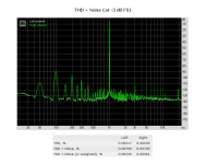
Made measurements U7 MK2 input - output no peaks at 50Hz. THD + Noise -92.2dB seems to be due to lme49726.
Attachments
Hi Per,
thanks for your offer! Information about how to put in EF transistors in the badly accessable space around the VAS transisitors are always welcome. Which mod on the IPS do you plan? emitter degeneration? some sort of current mirror load without operation point issues?
Best,
Sebastian
thanks for your offer! Information about how to put in EF transistors in the badly accessable space around the VAS transisitors are always welcome. Which mod on the IPS do you plan? emitter degeneration? some sort of current mirror load without operation point issues?
Best,
Sebastian
Hi Sebastian,Hi Per,
thanks for your offer! Information about how to put in EF transistors in the badly accessable space around the VAS transisitors are always welcome. Which mod on the IPS do you plan? emitter degeneration? some sort of current mirror load without operation point issues?
Best,
Sebastian
I am using emitter degradation in my other Mk2 upgrades, theoretically it is quite easy, although in practice often less so, dependent on the pcb layout - and the skills of the person with the soldering iron. More on this and the use of current mirrors in the upcoming series of posts on the 971.
Even though I can understand your reluctance in going deep into this rather convoluted amp design more than once, I would strongly recommend to take things one step at a time.
You know: One change - double check - test - review voltages and temperatures - then to next step. And use a dual bench power supply with current limiting if you possibly can. If you don't have one, try to beg, steal or borrow a pair from someone - even if they cant provide the full rail voltages.
Always ensure that things are stable and turn back the bias before moving back to the high power amp supply.
Modifying under full reservoir power is a bit like sorting your stash of fireworks with a lit torch, if you know what I mean.

Before starting. I would first make sure that the bias is zero and replace the fuses with some low value, say 500mA (not that fuses are much of a guarantee - as transistors are commonly known as TLFP, Three Legged Fuse Protectors).
Then move to the bench power with the current limiting set to 50-100mA before doing the mod - double check again - and powering up. If all is good, you should see the current limiting kick in as you turn up the bias - briefly if you haven't clamped any heat sinks on the power transistors.
Being careful and patient can save you from blue smoke surprises, but not at least because replacements for the old trannies in this amp are getting harder to find and obtain.
I will try to find my old 991 instructions and post them here. You should make sure that the RB-990 pcb's are the same as the RB-991's.
Best,
Per
PS. Apologies if you already knew all this, it is definitely not my intention to sound condescending to anyone on this thread.
Last edited:
Hi Per,
Made measurements U7 MK2 input - output no peaks at 50Hz. THD + Noise -92.2dB seems to be due to lme49726.
Hi Sam,
That looks a bit better - and the strange spike at 11kHz(?) is gone. I still question the distortion spikes though, particularly the 3rd harmonic.
Anyway, you got me thinking.
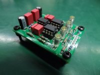
I have been struggling with some sort of 50/100Hz hum issues in my RTA's - discussed earlier in this thread.The U7's input is unbalanced and I think it was sgrossklass that suggested to use an INA (Instrumentation Amplifier) before the U7 to filter out any common mode hum.
I have recently made a 'noise cancelling' phono preamp with INA117's (see pic) which I may consider to use (after of course pulling the RIAA de-emphasis stuff out).
But..... that is still yet another project on my ever growing to-do list.
Per
Attachments
Hi Per,
thank you for your wise words. I was aware of a few points, but you given me also new informations. I have already realised that I need to create the possibility to operate a board outside the housing. I will use a lower voltage power supply for the modding process, but with current limiting - this is a nice wish, but I must go without it. I have already head scrached how to mod with the heatsink on, but with zero bias it may work without the heatsink. I will double check with some calculations.
There are two points on these PCB to think on: 1. The protection circuit -> This should not be a problem. The amp should start, without both ribbon cables attached - without the input mute function. 2. VERY IMPORTANT -> The feedback point is taken of on the binding post and is feeded back to the PCB by a separate wire. When the board is taken out of the amp, this point on PCB MUST be connteted to the output to close the feedback loop again!
I took the right channel board already out of the amp and I will prepare my workbench and then I come back to here.
First step will be cleaning the PCB and removing the brown glue (Brown glue is known to become conductive with time). Then the convertion to Miller compensation. Then ....
Best,
Sebastian
Hi all - greatings from The Netherlands !
I have been reading this tread with great interest, and happily found out that this is still an active one as we speak.
As short intro: I am running Scanspeak speakers (Ellam 3W from Troels Grevsen) in a bi-amp setting with an active cross over at ca. 300 Hz.
This currently runs on 2 older Pioneer A-656 amps but I recently found a Rotel RB-976 (6 channel) in an attempt to move to a more compact solution.
So step one was to dismantle and clean the Rotel, and I am now ready for replacing caps and maybe adding some of the mods discussed here.
It will also require a DC protection circuit at the end of the line, unbelievable that Rotel dared to ship amps without such safety net !!
This thread is a good reference since the power amp section is pretty identical to the 820AX here !
Therefore I would be interested to learn from Per or others what the final "happy status" is on your 820AX-s,
I read various mods that were removed again later, so very interested to learn where you are now at, I will also share my devdlopments here.
Thanks all,
Dirk
Hi Dirk,
The "happy status" of the RA-820AX (and the RA-930,931,01,02,03,04, etc.) is unchanged and "happy".
The upgrades never ceases to bring out a "WOW, unbelievable" from the owners of these amps, the improvements are really that audible.
And these reactions from people is why I still do them in a steady stream across the workbench - although it is now routine and the original excitement of accomplishment has maybe waned somewhat.
And yes, I put in speaker protection in the Rotels that do not have any. I have never done a RA-976 so I don't know how much room there is for six protection circuits - you'll have to figure that out. Otherwise, the only change is that I skipped the rail filters to the input stage. If the LTP's are perfectly matched the PSRR of the amp will do their job nicely - and save a lot of track cutting and component fitting.
But six channels will still be quite some work and comes with a cost, I sell the modules for £10 each - and you need two per channel. But the result is definitely worth the effort.
Best,
Per
Hi Per thanks for the quick reply.
Due to my bi-amp requirement it could consider leaving out the heatsink in the middle and disengage 2 of the 6 channels, that would create plenty of room for DC protection for the remaining 4 channels; these modules can easily be connected / soldered to the fuse-holders that are now supposed to protect the LS's.
I will in any case adopt the 100 Ohm / 10u / 100n in the power lines to the input stages
What is now your final modification to the input stages and the VAS circuitry ? Can you share the schematics as you now run them ?
I also noticed that the power stages contain 2SC5200/2SA1943 matched pairs, whereas service manual schematics specify other part.nrs, are you familiair with variations in this ? All 6 pairs look identical so the must be original parts from factory. I also have various original 2SA1302/2SC3281 pairs from older scrapped Pioneers
Hi Dirk,
I think that I used 100ohm / 100uF filters, but that is now history.
I wonder whether the 5200/1943 output trannies are factory originals - or been replaced at some later time, but anyway they are good trannies and will definitely do the job so I would leave them in.
I haven't drawn a "final" schematic of the upgrades but will try to find the time to do so.
Best,
Per
Hi Per,
thanks for your offer! Information about how to put in EF transistors in the badly accessable space around the VAS transisitors are always welcome. Which mod on the IPS do you plan? emitter degeneration? some sort of current mirror load without operation point issues?
Best,
Sebastian
Hi Sebastian,
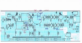
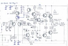
I enclose the pic of the EF-VAS upgrades Smartdriver did on the RB-991. Note that on the pcb we replaced R607/608 with one of the 2k2 EF emitter resistors. The 607/608 1k5 was relocated to a new position by the LTP transistors. You will of course have to drill some holes - as when installing the NPN EF around the track cut.
I noticed that I forgot to draw the 47p Miller capacitors on the Rch. They should all four be NPO and sit safely on the solder side of the pcbs.
I also noticed that I wrote "2 x KSA992" on the schematic - one should of course be a KSC1845 NPN.
The 992 PNP EF that sits in place of the J111/112 jumper has the collector lifted and a wire attached for connection to the ground. Note the TO-92 orientation.
Again, please make sure that this will fit on your RB-990 pcbs! I haven't checked that.
The four VAS emitter resistors were increased to 187R to reduce the current and temperature in the VAS. Smartdriver also did some nice looking work on the heatsinks to further increase the cooling. And of course the 33k was removed and the 330pF replaced with a 15pF NPO.
I will cover the LTP emitter degradation and current mirror work in the upcoming RA-971 posts.
Best,
Per
Attachments
Привет Пер,
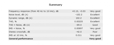
Измерено RA-972, заводские общие гармонические искажения (20 Гц-20 кГц) < 0,03% при номинальной мощности, 1/2 мощности или 1 Вт. Интермодуляционные искажения (60 Гц : 7 кГц, 4:1) < 0,03% при номинальной мощности, 1/2 мощности или 1 Вт. Отношение сигнал/шум (взвешенное IHF «A») >95 дБ.
Пер, как ты избавился от басового шума Asus Xonar U7 MKII?
Attachments
Hi Per thanks for the quick reply.
Due to my bi-amp requirement it could consider leaving out the heatsink in the middle and disengage 2 of the 6 channels, that would create plenty of room for DC protection for the remaining 4 channels; these modules can easily be connected / soldered to the fuse-holders that are now supposed to protect the LS's.
I will in any case adopt the 100 Ohm / 10u / 100n in the power lines to the input stages
What is now your final modification to the input stages and the VAS circuitry ? Can you share the schematics as you now run them ?
I also noticed that the power stages contain 2SC5200/2SA1943 matched pairs, whereas service manual schematics specify other part.nrs, are you familiair with variations in this ? All 6 pairs look identical so the must be original parts from factory. I also have various original 2SA1302/2SC3281 pairs from older scrapped Pioneers
Hi Dirk,
I just noticed the huge differences between the RB-976 and the RB-976 MkII (at least compared to the RA-931 vs. RA-931 MkII which was merely a change of the opamp in the preamp stage).
Anyway, the RB-976 MkII uses the 2SC5200/2SA1943 power trannies - so maybe they just sneaked some into a few late production runs of the RB-976?
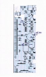
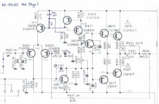
I enclose my schematic of the basic upgrades, it is based on the 820AX schematic, but I think that it also fits your 976. This will give you the most "bang for the buck" with a minimal effort. No pcb drilling or track cuts and everything is reversible, if needed.
Note that some of the changes are already done on your 976 pcbs, and the fuse and bypass resistor should be replaced with a speaker protection module. Oh, and 27p C609 is already on the VAS3 module, and you can either remove the 150p C609 or leave it in.
The tricky thing is placing the 68R emitter degradation resistors, I will try to take a picture of how I do it.
Hope this helps you.
Happy modding!
Per
100ohm / 100uF filter
This filter is required, I have 470 mkF 33 Om.
Hi Per,
Measured RA-972, factory total harmonic distortion (20Hz-20kHz) < 0.03% at rated power, 1/2 power or 1W. Intermodulation distortion (60Hz : 7kHz, 4:1) < 0.03% at rated power, 1/2 power or 1W. Signal-to-noise ratio (IHF "A" weighted) >95 dB.
Per, how did you get rid of the bass noise of the Asus Xonar U7 MKII?
Hi Per thanks a lot !
All 6 sets of 5200/1943 s look identical and PCB looks untouched so this may be a late MK1 with these components.
Still has no LS protection circuits. Unit is dimantled and well cleaned now.
From your previous posts I picked up attached 2 mods, should I disregard these ?
What are the types of the additional trannies ?
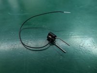
and the fancy looking duo, is that a special 2-in-1 component or a matched pair thermally coupled ?
cheers Dirk
All 6 sets of 5200/1943 s look identical and PCB looks untouched so this may be a late MK1 with these components.
Still has no LS protection circuits. Unit is dimantled and well cleaned now.
From your previous posts I picked up attached 2 mods, should I disregard these ?
What are the types of the additional trannies ?
and the fancy looking duo, is that a special 2-in-1 component or a matched pair thermally coupled ?
cheers Dirk
Attachments
Last edited:
- Home
- Amplifiers
- Solid State
- Improve a Rotel amp THD by 20dB!