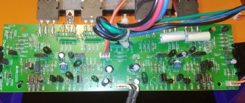
Ok, finally started work on first stereo board of 976 MK2. First step mostly audiofool changes. From technical changes replaced nfb capacitor with 220uf (from 100) and input ground resistor changed for same value as nfb resistor. I also need to replace current sources ground resistors for higher power rating because PCB under them is bit brown.
Next step will be ltp translator matching.
Next step will be ltp translator matching.
Attachments
Hello AngelIP,
I read all your post about refurbish RA_820xx, and that give me idea to refurbish my Rotel RA840BX2. What is my problem: i am not specialist to find out how implement idea from RA-820xx. So, wich capacitors and resistor need to replace? Only C1-C3? Which new one: type and factory?
There is picture about new grounding for 820, what for 840?
Any sugestion are wellcome. TIA!
Asim
Hi Asim,
Your RA-840BX2 is unfortunately the last of the Rotels that had its PCBs laid out by hand (or by tape, rather). And further, for some reason the layout is not done very professionally, so components are placed here and there and in different orientations.
This makes upgrading other than pure re-capping quite challenging and giving instructions even more so. 🙁
I have ever only done one 840BX2 - and as I remember I gave up on a lot of the usual upgrades I do, as it would involve a rats nest of airwires.
So if this is your first upgrade of an amp, I would definitely recommend getting a RA-931 instead. It is so much more straightforward to work on - and to get right.
Best,
Per
Capacitor type/make preferences have long been discussed and are clearly a matter of personal taste.
Some people can clearly hear sound differences where others can't. And..... I think I will leave it at that.
I have only a few basic principles:
If possible - change old electrolytic caps to new ones that fits on the pcb. Very often you will now get much better specs in the same can size.
In the audio path - if you can't DC couple - change to film caps or non-polarised electrolytics.
For power supply - go for low ESR and stability. Increase the capacitance, temperature and voltage rating where possible.
Then it of course comes down to price - and most particularly these days - availability.
So for your power supply I would change C903/904 to whatever quality reservoir caps you can find that fits in place. I use Elna LAO or Cornell-Dubilier (many other good quality brands are available). Be aware of height and diameter limits for the replacements if you want to be able to put the amp's top cover back on (yes, I have done that mistake).
Scrape off any old gunk/glue on the pcb and secure the new caps with a dot of glue. I use silicone.
And if you don't ever listen to vinyls - you are practically done!
As I remember, C907/908 are the unsightly caps that hovers at an angle over the pcb, making the design look quite messy? Maybe you could find more compact film caps and place them more neatly and securely. Leave the ceramic snubber caps C905/906 in.
For the phono stages I would use either film or Panansonic FM's. In the power stage, upgrade C605/606 to 220uF.
Have fun recapping and hopefully enjoy the rejuvenation and listening pleasure of your Rotel!
Best,
Per
Hello gents
I have discussed mod of power amp of rotel ra-01 and I would like to get second opinion here. I didn't find this mod here (or I do not realise it) and I wonder what do you say.
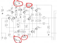
So the mod is to cut power supply for power amp and add RC filter and "come" closer with capacitors to some transistors in power amp. Suggestion is to add at least 470 uF capacitor, or 1000 uF better with 10 Ohm resistor.
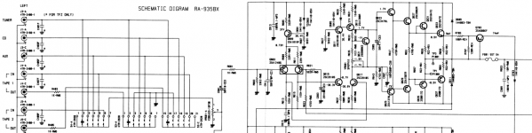
Enclosed scheme for one channel.
Thanks and hugs
I have discussed mod of power amp of rotel ra-01 and I would like to get second opinion here. I didn't find this mod here (or I do not realise it) and I wonder what do you say.
So the mod is to cut power supply for power amp and add RC filter and "come" closer with capacitors to some transistors in power amp. Suggestion is to add at least 470 uF capacitor, or 1000 uF better with 10 Ohm resistor.
Enclosed scheme for one channel.
Thanks and hugs
Attachments
Hi Piotrek,
Yes, that works. I did that at the very early stages of upgrading (see post #24/25) and it does reduce the input stage supply ripple.
You will lose a bit of headroom, but nothing serious.
However, I later found that if you actually manage to precisely match the input transistors the PSRR of the amp shoots up and practically makes this filter addition (which also requires cutting of pcb tracks, air-wiring, drilling holes and finding suitable spaces for the componets) - unnecessary.
And, being the lazy b*gger that I am, it suits me just fine.
Correctly matching of LTP transistors has been covered elsewhere on diyAudio. I found that it is most important to make sure that the trannies stay at exactly the same temperature during hFE and Vbe measurement. So I use a vice to clamp them while still sitting on the tape, measure every transistor twice and pencil down the result on the tape. Then it is easy to find matching pairs later.
Best,
Per
The reason for the high distortion of Rotel amplifiers is the poor layout of the "ground" buses on the printed circuit board. Due to the insufficient section on the tires, there is a noticeable voltage drop created by currents in the power circuits of the output stage. As a result, the ground potentials of the input stage and the ground of the output stage become different. There is a so-called distortion of the "reference potential" of the amplifier. This constantly changing potential difference is added to the useful signal voltage at the input and amplified by subsequent amplifier stages, which is equivalent to the presence of interference and leads to an increase in harmonic and intermodulation distortion.
t is also necessary to minimize the parasitic inductance of high-current power supply circuits of the amplifier. This can be achieved by installing additional conductors of a sufficiently large cross section along the power circuits of the output stage.
It is desirable to replace the diode bridge with discrete diodes with an extremely short reverse recovery time based on silicon carbide, for example manufactured by Infineon, which will add "dynamics" to the amplifier.
It is desirable to replace the diode bridge with discrete diodes with an extremely short reverse recovery time based on silicon carbide, for example manufactured by Infineon, which will add "dynamics" to the amplifier.
Last edited:
Hi Sam,
i think that is a little harsh verdict on the old Rotels. Yes, there are definitely improvements to be made, but generally I think that these Rotels easily hold their own against the other amps of their era, class and price range. Not least due to the layout and use of high current busbars in the power supply.
And if a THD spec. of 0.03% can be regarded as "high distortion", try doing a RTA on your £1000+ tube amp.
I have by now had at least a hundred different Rotels past my workbench and the "noticeable voltage drop created by currents in the power circuits of the output stage" has definitely eluded both me and my 6½ digit Keithley.
Actually, the whole idea behind this thread was to show that THD (and with that all the other distortion gremlins, cf. Chris’ post #81) can be substantially improved ’by 20dB to an audiophile level’ with only a few relatively simple measures – without performing radical reconstructive surgery on the amp.
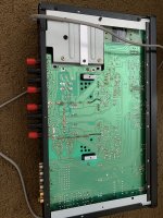
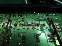
That said, you are right about the high currents inthe power supply. This is particularly true in the ground star connections and I always add a strip of copper braid between the ground potential terminals and the black return wire to the transformer, see pic 1. It could perhaps be argued that the trafo wires could be thicker, but there is not much we can do about that.
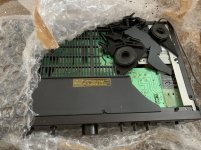
The RA-930/931 series of course also have a basic design flaw in the use of a plastic bottom panel and an insufficiently rigid transformer base screwed directly onto it for support. Many of these amps end their days after a courier transport – particularly if you label the box ”FRAGILE” – apparently, that is like waving a red blanket in front of a bull.
Typical result - Pic 2, ageing plastic gets brittle and these spare parts are rarer than ’hens’ teeth’.
My solution – Pic 3, a stabilising bracket under the base and removing the two screws to the pcb and bottom panel. This effectively stops the trafo from vibrating and saves the plastic panel for another 30 years of service.
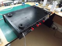
If the damage is already done, I have made replacement panels from perforated Al sheet with some snazzy black or gold feet to spice up the looks, Pic 4. Gives a better shielding than the thin alu tape on the plastic - and slight reduction in 50/100 Hz too.
There is always hours of fun to be had with these amps!
Per
i think that is a little harsh verdict on the old Rotels. Yes, there are definitely improvements to be made, but generally I think that these Rotels easily hold their own against the other amps of their era, class and price range. Not least due to the layout and use of high current busbars in the power supply.
And if a THD spec. of 0.03% can be regarded as "high distortion", try doing a RTA on your £1000+ tube amp.
I have by now had at least a hundred different Rotels past my workbench and the "noticeable voltage drop created by currents in the power circuits of the output stage" has definitely eluded both me and my 6½ digit Keithley.
Actually, the whole idea behind this thread was to show that THD (and with that all the other distortion gremlins, cf. Chris’ post #81) can be substantially improved ’by 20dB to an audiophile level’ with only a few relatively simple measures – without performing radical reconstructive surgery on the amp.
That said, you are right about the high currents inthe power supply. This is particularly true in the ground star connections and I always add a strip of copper braid between the ground potential terminals and the black return wire to the transformer, see pic 1. It could perhaps be argued that the trafo wires could be thicker, but there is not much we can do about that.
The RA-930/931 series of course also have a basic design flaw in the use of a plastic bottom panel and an insufficiently rigid transformer base screwed directly onto it for support. Many of these amps end their days after a courier transport – particularly if you label the box ”FRAGILE” – apparently, that is like waving a red blanket in front of a bull.
Typical result - Pic 2, ageing plastic gets brittle and these spare parts are rarer than ’hens’ teeth’.
My solution – Pic 3, a stabilising bracket under the base and removing the two screws to the pcb and bottom panel. This effectively stops the trafo from vibrating and saves the plastic panel for another 30 years of service.
If the damage is already done, I have made replacement panels from perforated Al sheet with some snazzy black or gold feet to spice up the looks, Pic 4. Gives a better shielding than the thin alu tape on the plastic - and slight reduction in 50/100 Hz too.
There is always hours of fun to be had with these amps!
Per
Attachments
Hi Per,
What I have said applies to most amplifiers of this class, not only Rotel.
Power ground and power circuits can be duplicated with strips of copper foil of the appropriate size. I applied 0.4x10mm placing them at a 90 degree angle to the mounting tracks. The main condition is that the magnetic fluxes do not intersect.
Another effective solution is a capacitor (sometimes not found in the circuit) shunting the alternating current, although low, but the collector-emitter resistance of the bias transistor. Jelmax, calls this capacitor (Vita-drive circuit), recommending to put a capacitor there with a capacity of at least 470 uF and, of course, non-polar.
It was 470 uF x 6.3 V BG N that I set in bias and OOS, but it is expensive and no longer available, so you can use another non-polar one. When we use a conventional capacitor, then on weak signals it has losses caused by the polarization of the dielectric layer and significant (for weak signals in the CNF circuit) distortion (i.e., essentially incorrect information for the CNF circuit). The remaining electrolytic capacitors in the signal circuit have been removed.
Another simple tweak. With the help of a couple of pieces of a shielded cable, the OOS signal is fed from the output relays directly to the differential stage. Physically, this circuit is located on the board and is connected to the output also on the board. Since the current in the output circuit is very significant, the OS signal comes through the same wire as the output current, therefore, the OS signal is distorted.
The above changes do not require changes in the lighting technology of the amplifier and are quite affordable.
Last edited:
When choosing capacitors in correction circuits - foil polypropylene WIMA FKP, Rifa PHE, Siemens B, foil polystyrene REL-CAP, PHILIPS KS, Rifa PFE, PHILIPS KS, WIMA FKC3 foil polycarbonate, Cornell Dubilier mica, the best NPO multilayer ceramics turned out.
The 50kΩ volume control is large enough as a preamp control. The Rotel RA 935 circuitry has a shorter path and a 20kΩ potentiometer instead of the usual 50kΩ potentiometer to reduce amplifier noise. Modern sources provide the required output signal level and can operate on a fairly low-resistance load.
The 50kΩ volume control is large enough as a preamp control. The Rotel RA 935 circuitry has a shorter path and a 20kΩ potentiometer instead of the usual 50kΩ potentiometer to reduce amplifier noise. Modern sources provide the required output signal level and can operate on a fairly low-resistance load.
Attachments
Hi Sam,
Firstly, I am not absolutely familiar with the acronyms that you use. Could you please write out OOS and CNF for me - and other readers of this thread?
Then for a cap around the bias transistor, that was discussed around post #320-23 and I think I found it to have very little (if any) audible or measurable effect.
It sounds like you have actually done the improvements that you suggest – have you got any pictures and before/after measurements that you could share?
Per
I have read the VHa Drive page a couple of times and am still rather confused. Is it a computer generated translation into English?
As best I can understand it, they are simply recommending using a special low ESR Black Gate capacitor around the bias transistor?
I've tried ultra-low ESR film, non-polar and very low ESR Panasonic FM caps - and still found no measurable or audible difference.
And I seem to remember that the Black Gates were discontinued by Rubycon years ago?
Per
I looked at post 320 on the answer Self claims that it helps speed up the on / off switching of the drivers - everything is correct. With a polar electrolyte in the bias circuit, at low signal levels, the distortion is large, and at a low capacitance, it also depends on the frequency. 100nf only helps switching at high frequencies.
Post 321 is correct. The musical signal is not a constant sine in frequency and amplitude.
Human hearing allows us to notice changes in a complex musical signal, but measuring equipment does not yet.
With a polar electrolyte in the OOS circuit, at low signal levels, the distortion is large. Better of course film, but its size. By using a non-polar capacitor in the OOS circuit, if we are left with OOS, which audiophiles do not like so much, it works much better, I would say more correctly.
Last edited:
- Home
- Amplifiers
- Solid State
- Improve a Rotel amp THD by 20dB!