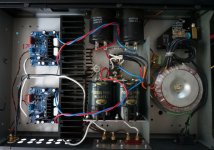
Here is a photo of the amp with one Vellemann replaced with a MX50SE, the other MX50SE waiting on top.
How the heatsinks ars cooled, I don't see any ventilation openings under them?
How the heatsinks ars cooled, I don't see any ventilation openings under them?
Now that the bias issue is sorted, it seems like the natural convection is sufficient, there is space under the heatsink and the top of the enclosure is perforated. If it turns out to run hot when used for extended periods, I can make openings in the base of the enclosure. This amp is mainly intended to be used for bench work (I build loudspeakers). My music amp is an old Accuphase
")
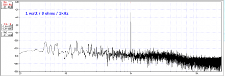
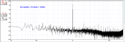
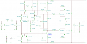
The THD on my MX50 is 0.0062% @1w / 1kHz and 0.0038% @ 44w / 1kHz
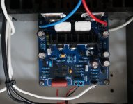
Mine is running 38-0-38 DC rails.
I have attached pics of my amp board so you can compare.
Mine is running 38-0-38 DC rails.
I have attached pics of my amp board so you can compare.
Attachments
Last edited:
As much as I love SMPS for audio, I would not recommend an SMPS for a power amp. SMPS are simply not suited for the large changes in load of a power amp.
But I sort of doubt that's the THD problem anyway. The fact that you have 200mVpp at 50Hz is a give away. SMPS do not emit 50Hz. They emit 50 KILO Hz. My guess would be that you're connecting your PC directly to the input and you're getting ground loop noise. The MX50SE is single-ended. You must put a differential input in front. Or use a transformer. Ideally a 10K line input transformer. Although I used some 600R bullet transformers I had laying around with 10K pots on the secondary and that works just fine.
As for bias, my first thought would be that you've had a bit of bad luck with the input transistors supplied in the kit and they're just not matched closely enough and you're getting some offset on the output. When I first built these kits, one had an offset of 34mV. That's not enough to make anything hot but what offset are you measuring?
Or it could be that one of your output transistors is not thermally bonded to the heat sink properly and the temp differential is causing some offset. When you measure offset, leave the amp on for 20min and then measure.
Or it could be that the "rubber diode" bias transistor (Q9 in my schem) is bad or wrong somehow.
I doubt that it's oscillation. For oscillation to make the amp hot, it would have to be clipping the amp but you would see that pretty clearly. The whole oscilloscope display would light up. Unless maybe the scope or scope probe has some kind of low pass filter engaged.
Incidentally the inductor || resistor in parallel is for isolating capacitive loads which would only be applicable if you're driving really long cables. Also, you don't want the resistor to be smaller because all current is through the inductor at audio frequencies. At higher frequencies, the inductor is high impedance and so the load then sees the higher impedance of the resistor. So the resistor should be more like 40 ohms and not 4 ohms.
BTW, I have used my MX50s daily since I originally posted about this. Never had a problem with them, they sound great and they're super quiet. With the inputs terminated and the amps cranked 100%, there is NO hiss whatsoever. The MX50SE is basically a discrete op amp hardwired for 30x gain or whatever it is. The Sziklai output pairs add significant open loop gain and swing to the rails. They're great amps.
I put 'ground break resistors' on mine, maybe that could help if someone has problems with ground loop hum. On the newer boards there is a thin trace between signal ground and power ground next to the GND connector (component side), this can be cut, and a small value resistor soldered in. On the older boards there is a small choke in this position that can be replaced with a resistor.
yes ground loops can be an extremely annoying problem. I have inserted a ground lift switch on my amp - when lifted two large parallel, opposing diodes and 100nF connect ground/chassis to mains earth - to keep it safe! I also found that running balanced from my new DAC across to the amp, ands shorting one lead to gnd at the amp side is much more quiet than running unbalanced across the room.
As much as I love SMPS for audio, I would not recommend an SMPS for a power amp. SMPS are simply not suited for the large changes in load of a power amp.
But I sort of doubt that's the THD problem anyway. The fact that you have 200mVpp at 50Hz is a give away. SMPS do not emit 50Hz. They emit 50 KILO Hz. My guess would be that you're connecting your PC directly to the input and you're getting ground loop noise. The MX50SE is single-ended. You must put a differential input in front. Or use a transformer. Ideally a 10K line input transformer. Although I used some 600R bullet transformers I had laying around with 10K pots on the secondary and that works just fine.
As for bias, my first thought would be that you've had a bit of bad luck with the input transistors supplied in the kit and they're just not matched closely enough and you're getting some offset on the output. When I first built these kits, one had an offset of 34mV. That's not enough to make anything hot but what offset are you measuring?
Or it could be that one of your output transistors is not thermally bonded to the heat sink properly and the temp differential is causing some offset. When you measure offset, leave the amp on for 20min and then measure.
Or it could be that the "rubber diode" bias transistor (Q9 in my schem) is bad or wrong somehow.
I doubt that it's oscillation. For oscillation to make the amp hot, it would have to be clipping the amp but you would see that pretty clearly. The whole oscilloscope display would light up. Unless maybe the scope or scope probe has some kind of low pass filter engaged.
Incidentally the inductor || resistor in parallel is for isolating capacitive loads which would only be applicable if you're driving really long cables. Also, you don't want the resistor to be smaller because all current is through the inductor at audio frequencies. At higher frequencies, the inductor is high impedance and so the load then sees the higher impedance of the resistor. So the resistor should be more like 40 ohms and not 4 ohms.
BTW, I have used my MX50s daily since I originally posted about this. Never had a problem with them, they sound great and they're super quiet. With the inputs terminated and the amps cranked 100%, there is NO hiss whatsoever. The MX50SE is basically a discrete op amp hardwired for 30x gain or whatever it is. The Sziklai output pairs add significant open loop gain and swing to the rails. They're great amps.
@miallen, the bias problem/running hot issue is fixed, it was the Q7 669 that had to be replaced. Amp running normally now, no hiss or hum or DC offset. Re, SMPS - if these are suitable for power amps or not, I suggest it depends on the SMPS - but it is indeed very odd I have 50 hz on the rails - that is definitely worth investigating. I shall check if there is less distortion and noise when running on the bench supply.
Re. the R||L output network - According to a number of amp schematics, it seems that L is generally around 2-3 uH, while R is in the range 2 - 10 ohm. If one plans to use a particular cable, I guess the R||L circuit can be designed accordingly or omitted. In any case the network operates above 100 kHz so it should have little impact on sound.
<snip>
As for bias, my first thought would be that you've had a bit of bad luck with the input transistors supplied in the kit and they're just not matched closely enough and you're getting some offset on the output. When I first built these kits, one had an offset of 34mV. That's not enough to make anything hot but what offset are you measuring?
DC offset won't make the outputs hot - not unless there's a huge offset and a load is connected of course. But in that case there would be a fault...
Or it could be that one of your output transistors is not thermally bonded to the heat sink properly and the temp differential is causing some offset. When you measure offset, leave the amp on for 20min and then measure.
The MX50 is a CFP design, so the thermal compensation is derived from the drivers rather than the output transistors.
Or it could be that the "rubber diode" bias transistor (Q9 in my schem) is bad or wrong somehow.
It sounds as though this is what the OP has since found and corrected now.
I doubt that it's oscillation. For oscillation to make the amp hot, it would have to be clipping the amp but you would see that pretty clearly. The whole oscilloscope display would light up. Unless maybe the scope or scope probe has some kind of low pass filter engaged.
I've had amps oscillating cleanly at 300.. 500kHz - a beautiful low THD sinewave.
And a very hot output stage to go with it.
The amp played fine, although there was a hint (apart from the heat) that something wasn't right, as there was a lot of sibilance.
Incidentally the inductor || resistor in parallel is for isolating capacitive loads which would only be applicable if you're driving really long cables. Also, you don't want the resistor to be smaller because all current is through the inductor at audio frequencies. At higher frequencies, the inductor is high impedance and so the load then sees the higher impedance of the resistor. So the resistor should be more like 40 ohms and not 4 ohms.
In his book, Bob Cordell recommends 2 - 8 ohms. 40 ohms is too high.
BTW, I have used my MX50s daily since I originally posted about this. Never had a problem with them, they sound great and they're super quiet. With the inputs terminated and the amps cranked 100%, there is NO hiss whatsoever. The MX50SE is basically a discrete op amp hardwired for 30x gain or whatever it is. The Sziklai output pairs add significant open loop gain and swing to the rails. They're great amps.
You're not confusing the MX50SE with the MX50X2 are you?
The MX50 is a standard CFP design with complementary NPN/PNP transistors, but the MX50X2 has a quasi-complementary output stage, with the bias compensator mounted on the main heatsink.
<snip>
Re. the R||L output network - According to a number of amp schematics, it seems that L is generally around 2-3 uH, while R is in the range 2 - 10 ohm. If one plans to use a particular cable, I guess the R||L circuit can be designed accordingly or omitted. In any case the network operates above 100 kHz so it should have little impact on sound.
I also have an L20SE (my current main amp) and this doesn't have an output inductor either. I fitted a 1.5uH inductor with a 2 ohm resistor in parallel, and I it seemed to get rid of sibilance. My theory is that the amp was oscillating* with certain frequencies into some loads (it was clean into a resistive dummy load, even at 4 ohms).
*the oscillation being triggered by specific frequency / load conditions.
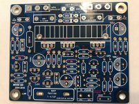
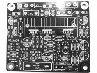
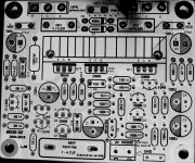
Component location on MX50SE board
Hello all... I used the schematic that slowhands uploaded to this thread...
MX50SE LJM 2015
and labeled the board with component locations.
I just got the boards last week and purchased a set of 2sa1186 and 2sc2343 from Digi-Key.
One question is on the schematic it shows R3 and R29 as 68 ohm but my board shows them at 47 ohm. Should I leave them at 47?
Thanks all for all the info on these boards..
Hope it helps someone.
Attachments
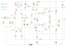
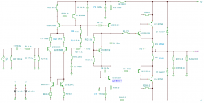
MX50SE actual schematic
Here's the actual schematic for the MX50SE - I reverse engineered this from a board I bought about 10 months ago.
As this was drawn for Spice you can ignore the voltage source at the input, and the resistor (RLOAD).
Here's the actual schematic for the MX50SE - I reverse engineered this from a board I bought about 10 months ago.
As this was drawn for Spice you can ignore the voltage source at the input, and the resistor (RLOAD).
Attachments
- Status
- This old topic is closed. If you want to reopen this topic, contact a moderator using the "Report Post" button.
- Home
- Amplifiers
- Solid State
- MX50SE LJM 2015