any one here work on one of these before ?
i just need to know the resistor next to the x2 rated cap on the front panel board , what it job in the front panel circuit ? mine is just smoked , but i need to find out what cause it to overheat .
attathed is the pictures of the board and resistor in question.
thanks
Peter
i just need to know the resistor next to the x2 rated cap on the front panel board , what it job in the front panel circuit ? mine is just smoked , but i need to find out what cause it to overheat .
attathed is the pictures of the board and resistor in question.
thanks
Peter
Attachments
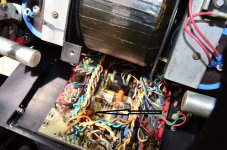
I have one sitting here that I just finished last week. The resistor is a 11kohm/2 Watt carbon comp that appears to just power the front panel LED. That's all I can tell by just looking behind the front panel. I am NOT going to disassemble it again, too much time involved.
Craig
Craig
Thanks Guys.
yes the resistor is 11K as Graig have said ( brown-brown-Orange ).
this amp first fired some of the 4700pf x2 rated caps in near by area with this is resistor . i changed those and now this resistor firer , hence my reason to findout what cause and what this resistor function in this board .
also Graig. did you have to adjust the bias on this amp after you done the repair ?
Cheers
Peter
This amp came to me with shipping damage and that's all I repaired. Replaced all 12 of the big PCB mounted electrolytic capacitors (because several broke off), transistor insulators, and thermal compound. I did NOT adjust the idle current because I couldn't find a reliable source on how to do so. I measured THD at 20, 200, 2k, and 20kHz at 2, 20, 200 Watts all were in .00x range or so and it idles only warm so I figured I'd just leave it. Did I mention these are a PITA to work on?
Craig
Craig
Last edited:
This amp came to me with shipping damage and that's all I repaired. Replaced all 12 of the big PCB mounted electrolytic capacitors (because several broke off), transistor insulators, and thermal compound. I did NOT adjust the idle current because I couldn't find a reliable source on how to do so. I measured THD at 20, 200, 2k, and 20kHz at 2, 20, 200 Watts all were in .00x range or so and it idles only warm so I figured I'd just leave it. Did I mention these are a PITA to work on?
Craig
Thanks Graig.
indeed it is very time consuming to work on this amp . too many screws to take off
")
nice to know you replace the caps . can you kindly let me know where you souse the caps ? i might consider change them on mine too .
i ask about the bias is that I can see after i run mine for around 15 mins one side of the heatshink seem a bit warmer than the other side therefore i think one channel bias might be off a bit ? no ?
cheers
Peter
In order to replace those capacitors the PCB needs to removed from the heat sink. All of the TO-3 transistors are soldered to the double-sided board thru eyelets making them very hard to remove without damaging the board. So unless you have a very strong desoldering station I would leave the caps alone unless the PCB needs to be removed for other reasons.
I used the only caps I could find in the short time I had to do the job. They were Nichicons from Mouser. The 680uf and 330uf 100v caps had to be increased to 200v as that's all I could find. The original caps are long gone.
Craig
I used the only caps I could find in the short time I had to do the job. They were Nichicons from Mouser. The 680uf and 330uf 100v caps had to be increased to 200v as that's all I could find. The original caps are long gone.
Craig
for additional pictures check out this thread:
Mark Levinson No23 repair help
who can upload the schematic ?
Mark Levinson No23 repair help
who can upload the schematic ?
- Status
- This old topic is closed. If you want to reopen this topic, contact a moderator using the "Report Post" button.
- Home
- Amplifiers
- Solid State
- need some help on my Mark Levinson No23