

Hehh! I'd like to see just ONE working, tested, documented (photos, screenshots, PCB layout, etc.) design from our resident audio magician!......")
He has them all on his site. His EF3's would oscillate ??
OS
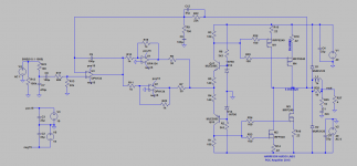
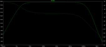
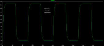
My first rule is if it needs a choke on the output it better be a impedance coupled RF amplifier. The Vout graph shows almost zero phase margin so under any real speaker load this will oscillate. Maybe a better oscillator than amplifier? Gain on the output stage? Back to that known load and RF applications. Usually gain on the output is not so stable (do not nit pick this) with unknown loads but, can be made so with a lot more parts. So many slop amps in the feedback loop. What is the propagation time through this amp, half a day? Parallel op amps for more power out? Choose a better op amp as this really does not work that well. Same for parallel output, use one pair of outputs or more than ten pair.
Suppose I am to picky for you guys...just as I am.
Suppose I am to picky for you guys...just as I am.
Thanks Hugh, hope you like the method used although members are welcome to whip up their own renderings.Any ideas about the feedback?
Hugh
Happy new year !
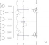
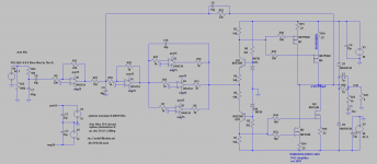
I see: many inputs , balanced , no feedback ,no output , and where are voltage rails?
secret one?
Alex
Thanks Alex, am hoping you will be one of those members who are going to road test this one
. Thanks for the good job with the SYMEF.Thanks OS. Kindly post your build for debuggingHe has them all on his site. His EF3's would oscillate ??
OS
There is a certain, unfortunate similarity to Stee's cut/paste electronic graphics.
I think we are only asked to consider the possibility of driving a Mosfet output stage with enough parallel opamps for the power required.
Does that make it a POC? .....dunno yet
Thanks Ian this is quite the POC
am hoping you will be one of those members who are going to road test this one .Thanks Lazy Cat. This amplifier is another whole story. There are simply no claims. The builder will start his builds with no hints on what they expect to hear. Interestingly though its results are important.So that's how "The Formula" evolves?!
Thanks for joining us. Now backup your take...build, test and improveMy first rule is if it needs a choke on the output it better be a impedance coupled RF amplifier. The Vout graph shows almost zero phase margin so under any real speaker load this will oscillate. Maybe a better oscillator than amplifier? Gain on the output stage? Back to that known load and RF applications. Usually gain on the output is not so stable (do not nit pick this) with unknown loads but, can be made so with a lot more parts. So many slop amps in the feedback loop. What is the propagation time through this amp, half a day? Parallel op amps for more power out? Choose a better op amp as this really does not work that well. Same for parallel output, use one pair of outputs or more than ten pair.
Suppose I am to picky for you guys...just as I am.
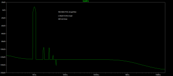
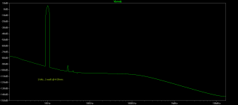
THD
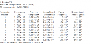
The THD is at 0.001% at one watt and 0.003% at full power. Being a compound amplifier its more of an engineering excursion. Both this and the FS model will have PCBs by Christmas , but early adopters are now good to go for the POC, however note the lack of bias adjustment and is manual through trial and error. Device matching at this stage is recommended. Only the output devices are on heat sink. Thermal stability not an issue. Feel free to share your own adjustments and results
The THD is at 0.001% at one watt and 0.003% at full power. Being a compound amplifier its more of an engineering excursion. Both this and the FS model will have PCBs by Christmas , but early adopters are now good to go for the POC, however note the lack of bias adjustment and is manual through trial and error. Device matching at this stage is recommended. Only the output devices are on heat sink. Thermal stability not an issue. Feel free to share your own adjustments and results
We can build as is then from there see what else we can improve, what did you have in mind
You'll need thermal compensation for the OPS. Freq. compensation and pcb will be problematic, possible oscilations etc.
Yup the phase margin is living on the edge, however the amplifier might not be unstable(to be taken with a pinch of spice), quite an exciting project really. The zobel should be just fine where it is, however am open to mods. Kindly share your mods
The Zobel network is the wrong side of the inductor surely? its being shielded from the amp by said inductor. Phase margin living on the edge as mentioned!
- Status
- This old topic is closed. If you want to reopen this topic, contact a moderator using the "Report Post" button.
- Home
- Amplifiers
- Solid State
- POC amplifier