See this thread. http://www.diyaudio.com/forums/solid-state/211905-diyab-amp-honey-badger-build-thread.html
There is a build document in there somewhere that tells what all the parts are , what they do, and the schematic. I've learned a lot of useful acronyms thrown around here from reading it.
If your transformer is a little low in voltage, it decreases your chance of an overheated part, at the expense of a decibel or two of loudness.
The rating of the speakers you are driving is important. You should measure them to make sure the resistance is at least 3.5 ohm (4 ohm impedance). Have a stock resistor lower than 10 ohms as a calibrator, DVM's are badly affected by the battery at this low impedance.
The transistors listed are difficult to source in the USA, but I use equivalents in polarity, Vceo, and package style with mostly success.
Sometimes the diyaudio store has kits for these, some with parts, some without, its up to you. Sometimes they are out. See the fifth link on the blue bar ol the solid state thread.
Have fun.
Thanks for reply.This is last one i did,working fine i adjusted bias 50mA.Like all the time i get heat Q6 and Q8 gets hot.If play 10min it is ok but i dont think it will last longer.Whats wrong people with this circuit.I have 2x50AC 500Va transformer,it is quite enough to drive this circuit
I suggest the circuit is fine and the author has a commercial forum here if you wish to ask him whether he has published a non-working circuit, for yourself:
http://www.diyaudio.com/forums/aussie-amplifiers/
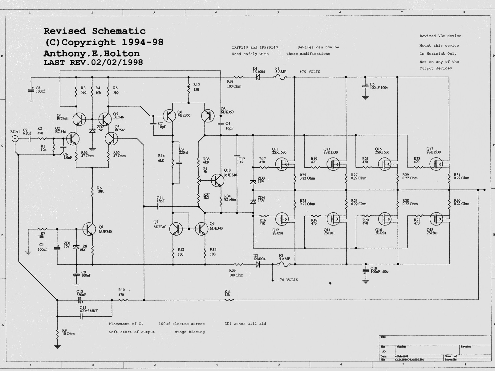
The schematic is clearly his copyright and this is the wrong place to post it unless you have his permission. As a comment, Q6,8 should get hot and will require a heatsink as they dissipate around 1.5Wea. With only a schematic , you are bound to make mistakes unless you have studied the component currents and dissipation.
http://www.diyaudio.com/forums/aussie-amplifiers/
The schematic is clearly his copyright and this is the wrong place to post it unless you have his permission. As a comment, Q6,8 should get hot and will require a heatsink as they dissipate around 1.5Wea. With only a schematic , you are bound to make mistakes unless you have studied the component currents and dissipation.
Ian Finch thanks for reply.I am not professional but MJE350 20W-300V-500mA transistor.I wonder how 20W transistor can get hot on 1.5W dissipating? I asked because on completed projects on internet i havent seen any heatsink attached to Q6 and Q8.
And i am living in country with limited possibilities.I cant order nothing from internet.we have only one electronic store here in the city.I hope Mr Holton doesnt mind") Sorry for posting.
Sorry for posting.
And i am living in country with limited possibilities.I cant order nothing from internet.we have only one electronic store here in the city.I hope Mr Holton doesnt mind
Sorry for posting.Hi Batson,
Simple calculation shows quiescent current through Q6, Q8 is around 5.7mA. So, woth +/-70V rails it give us around 400mW dissipation at each of Q6, Q8 and Q9.
At this level of dissipation these three will be rather warm, if not on a heatsink. If, as you say, they by some reason dissipate around 1.5W, they will be very hot.
You can check actual dissipation, measuring voltage drop over R15. Then divide it by 0.15 (R15 value in KOhm) and divide it by 2. This gives you actual quiescent current through each of the VAS transistors, mentioned above. Now multiply this value by C-E voltage and you have power dissipation value in mW. So, the question is - what is the voltage drop over R15? My calculation shows around 1.68V. What is the live measurement value?
Cheers,
Valery
P.S. Don't be fooled by 20W for MJE 340/350 - this is a maximum value, without a very good heatsink this kind of transistor will almost melt at this power At 1W it's already rather hot
Simple calculation shows quiescent current through Q6, Q8 is around 5.7mA. So, woth +/-70V rails it give us around 400mW dissipation at each of Q6, Q8 and Q9.
At this level of dissipation these three will be rather warm, if not on a heatsink. If, as you say, they by some reason dissipate around 1.5W, they will be very hot.
You can check actual dissipation, measuring voltage drop over R15. Then divide it by 0.15 (R15 value in KOhm) and divide it by 2. This gives you actual quiescent current through each of the VAS transistors, mentioned above. Now multiply this value by C-E voltage and you have power dissipation value in mW. So, the question is - what is the voltage drop over R15? My calculation shows around 1.68V. What is the live measurement value?
Cheers,
Valery
P.S. Don't be fooled by 20W for MJE 340/350 - this is a maximum value, without a very good heatsink this kind of transistor will almost melt at this power
At 1W it's already rather hot ...I have 50AC transformer...
It's obvious that you are looking for an amp sch. that will work fine with your transformer, but "50AC" means nothing - in order to get a good answer you have to provide good data.
So, what's the power and voltage rating of your transformer, one or more secondaries, center tapped... ?
vzaichenko Thank you lot.So how can i understand which transistor will handle the power.If Datasheet says 20Watts how i can understand it.Becasue 1.5Watts so few but it can get hot that transistor.
Can anyone post me good circuit?Did anyone tested 100%? I want to build very nice amplifier.People from all over the world
Can anyone post me good circuit?Did anyone tested 100%? I want to build very nice amplifier.People from all over the world
Batson, you misunderstand. The circuit you have is good and your transformer should be OK too.......Can anyone post me good circuit?Did anyone tested 100%? I want to build very nice amplifier.People from all over the world
However, you need to fit small heatsinks to keep those transistors cool as vzaichenko has further explained. If you want the amplifier to work you need to build it correctly. MJE340/350 have a hole for a 3mm bolt+mica pad and thermal grease to mount to a heatsink, similar to these pics:
An externally hosted image should be here but it was not working when we last tested it.
An externally hosted image should be here but it was not working when we last tested it.
vzaichenko you are right i measured R15 has 1.6Volts.
Ok looks like there is no way use it without heatsink.I dont wanted put a heatsink on board because it makes circuit bigger.Thank you guys.
Ok looks like there is no way use it without heatsink.I dont wanted put a heatsink on board because it makes circuit bigger.Thank you guys.
vzaichenko Thank you lot.So how can i understand which transistor will handle the power.If Datasheet says 20Watts how i can understand it.Becasue 1.5Watts so few but it can get hot that transistor.
Can anyone post me good circuit?Did anyone tested 100%? I want to build very nice amplifier.People from all over the world
Right, the power numbers in the datasheet assume your transistor has got enough heatsink to dissipate the heat. It's just not written there.
As Ian just mentioned, those transistors have got a hole just for that purpose - in most cases they need a heatsink (unless they work at very low voltages). Even a 150W transistor, loaded with 1.5W will get hot without a heatsink - it needs some way to dissipate those 1.5W.
Example - think what will happen if you remove the radiator from the car engine. What's going to happen? It will overheat all the time even at idle. Just because the heat needs to go somewhere
In some builds people prefer smaller heatsinks, but then they use fans to increase the airflow (and thus increase dissipation). Liquid cooling systems are also an option. But it's impossible to "trick the physics"
If you're looking for the compact amps with no (or very small) heatsinks - class "D" switching ones are your friends. But this is a very "different story"
Cheers,
Valery
Those TO220 heat sinks hit the cover of my amp, too. I've been making little heat sinks out of bits of scrap aluminum door frame channel, sawed up as low as I want, with a hole for the screw on the tab side and a couple of holes sprinkled around on the other two surfaces to encourage air flow. The height is just 8 mm, the wings are about 1.5 cm in a box shape. Seems to work on my 60 W/ch amp.
If you have problems getting parts through customs or $25 shipping charge or something, this solves those problems, also. You just need a hacksaw, a vise, a dirty shop, an assortment of small drills, and a hand crank drill like the Stanley. The electric drills with 12 mm chucks don't hold these little (3 mm, 4 mm) drills. Here in trash-it-all land, you can acquire 2 m of aluminum channel by just walking around early on garbage pickup day. Channel makes nice struts for bicycle baskets, too.
Another thing I do to increase survival of my DIY projects, is salvage 12 VDC fans out of dead PCAT ATX power supplies, mount them on a rail under the amp, and run them at 9 VDC from a wall transformer, blowing them on my heat sinks and boards. I have two like Mickey Mouse ears on my amp project, outside the case. I sawed the grills out of the PC case to put over the fans and keep the cat out of the fan. The fans saved my output transistors from overheating when the closed loop bias control circuit went open loop and the two O.T.'s ran at 440 ma idle bias current for months and months, who knows how long. That rediculous bias current sounded good, though.
Last edited:
Congratulations, it's good that it works but be specific. How much power are you using and how big is the power supply?
For example;
Assuming you are using the same 50-0-50 AC transformer you wrote about, The 500 VA rating will give maximum power, say 250W/8R, from 4 pairs of IRFP240/9240. Do you have the full number of 4 pairs fitted?
How much smoothing capacitance do you have for the power supply?
What is the power rating of your speaker and how loud is it playing before and after you increase the volume?
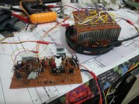
It appears from your pic. that the heatsinks are still way too small (if they do anything at all without that fan) and at the supply voltage you have (about +/- 70V), you should be using something much larger.
At least look at images on the internet, of Mosfet amplifiers rated for the power of this amplifier to get some idea of the size of parts needed. If you build a high power amplifier with tiny scrap heatsinks and tiny hookup wire, you can only expect that it won't perform properly and likely fail as you raise the power above 25% or so.
Fit proper heatsinks, use higher current rated leads for power, ground and output, like 10A minimum, if you want to keep power loss down. We can assume you didn't build such a large amplifier only to play at a few watts, so why not build it to match its design capability?
The image you just posted is for the PCB and components only. It does not show a likely huge heatsink that the power transistors are bolted to.
Read this thread or at least look at the pictures of the "Honeybadger" amp and understand how much cooling is needed for only 3 pairs of output transistors. 4 Mosfets pairs will need even more.
http://www.diyaudio.com/forums/solid-state/211905-diyab-amp-honey-badger-build-thread.html
For example;
Assuming you are using the same 50-0-50 AC transformer you wrote about, The 500 VA rating will give maximum power, say 250W/8R, from 4 pairs of IRFP240/9240. Do you have the full number of 4 pairs fitted?
How much smoothing capacitance do you have for the power supply?
What is the power rating of your speaker and how loud is it playing before and after you increase the volume?
It appears from your pic. that the heatsinks are still way too small (if they do anything at all without that fan) and at the supply voltage you have (about +/- 70V), you should be using something much larger.
At least look at images on the internet, of Mosfet amplifiers rated for the power of this amplifier to get some idea of the size of parts needed. If you build a high power amplifier with tiny scrap heatsinks and tiny hookup wire, you can only expect that it won't perform properly and likely fail as you raise the power above 25% or so.
Fit proper heatsinks, use higher current rated leads for power, ground and output, like 10A minimum, if you want to keep power loss down. We can assume you didn't build such a large amplifier only to play at a few watts, so why not build it to match its design capability?
The image you just posted is for the PCB and components only. It does not show a likely huge heatsink that the power transistors are bolted to.
Read this thread or at least look at the pictures of the "Honeybadger" amp and understand how much cooling is needed for only 3 pairs of output transistors. 4 Mosfets pairs will need even more.
http://www.diyaudio.com/forums/solid-state/211905-diyab-amp-honey-badger-build-thread.html
- Status
- This old topic is closed. If you want to reopen this topic, contact a moderator using the "Report Post" button.
- Home
- Amplifiers
- Solid State
- Need a working amplifier circuit please help