That looks better. You still have those dots in the silk though.
I got rid of some of them. Some are still a mystery. I will know to watch for them from now on. Too much into this one to worry about them. They are not hurting anything except the looks and all of them will be completely hidden once the parts are in place.
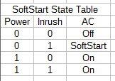
Yes that is correct except steps 3 & 4 are reversed. Inrush and Power overlap slightly.
Exactly
0...0 - Power Off
0...1 - Inrush
1...1 - Overlap
1...0 - Power On
The "inrush" circuit switches on first to feed the mains voltage (120Vac) through a resistor to ease the inrush of current into to the filter caps. After about three seconds the "power" circuit switches on to bypass the resistor. After that the "Inrush" circuit switches off to relieve the inrush relay draw from the 12Vac transformer.
What do you mean by the inrush circuit switches off?
Originally Posted by still4given View Post
The "inrush" circuit switches on first to feed the mains voltage (120Vac) through a resistor to ease the inrush of current into to the filter caps. After about three seconds the "power" circuit switches on to bypass the resistor. After that the "Inrush" circuit switches off to relieve the inrush relay draw from the 12Vac transformer.
I hope that is not the way it works.What do you mean by the inrush circuit switches off?
At Power ON the relays and controls should all be doing nothing.
The resistor current limiter should be in circuit.
Once the control circuit/s become active, the relay can activate to bypass the current limiting resistor/s. Thge relay is now active anmd draws coil energising current.
I see you asking a question, I will confirm that relay active after the delay is normal. Relay inactive (no current through coil) at start up and while power is OFF. This is the way most would design a control system.Inrush relay is Constanly on when it's activated?
A normal soft start (as different from a capacitor slow charge) is only needed until the transformer has built up it's operating flux to become a transformer, rather than a bundle of wire around a core. That start up for the transformer takes a few cycles of the mains waveform. It is generally recommended that the delay for the soft start be extended to be longer than 99ms.
Most adopt 100ms to 300ms. I can confirm that these delay timings all work.
There is no need to extend the soft start bypass delay to 3 seconds.
Last edited:
Yes, I can gather from your post that YOU do understand.
It's the others that don't, or can't write their thoughts unambiguously.
It's you that doesn't understand the circuit. Terry has it right.
This is a microcontroller based design. "Power on" is a sensed input to the microcontroller. The microcontroller controls all power to the rail supply transformer, and the optional tube heater relays. Any power to any part of the amplifier is fed through a series of relays. This gives the microcontroller the ability to turn off all power in event of trouble.
He queried his statement with
The relay de-energises to OFF, when the Power is turned ON?
That implies a relay is powered ON, when the power is actually switched OFF?
Does that mean his post was ambiguous?What do you mean by the inrush circuit switches off?
The relay de-energises to OFF, when the Power is turned ON?
That implies a relay is powered ON, when the power is actually switched OFF?
Last edited:
I know how soft start works☺
Just a bit confusing now, i just read linear protection 1.1 There is a good explanation ☺
The wiring to the relays has been changed slightly since Valery published that.
The Power relay needs to completely bypass the Inrush relay and resistor for operation. The Inrush relay is powered down after the power relay is activated to reduce power consumption. Earlier designs were causing the 12V regulator to run very hot if large relays were used and tube relay was present.
Thanks now i understand☺
One could use relay power savers to reduce the relay coil currents to lower, less hot values.
I regularly use 15V or 18V regulators to power on 12V relay coils.
I modified the DCB1 to do exactly that.
Power dissipation in the relay regulator went DOWN by implementing that modification and all it cost was an extra capacitor, the resistor was already there in case 5V relays were to be used.
I regularly use 15V or 18V regulators to power on 12V relay coils.
I modified the DCB1 to do exactly that.
Power dissipation in the relay regulator went DOWN by implementing that modification and all it cost was an extra capacitor, the resistor was already there in case 5V relays were to be used.
You queried his statement with Does that mean his post was ambiguous?
The relay de-energises to OFF, when the Power is turned ON?
That implies a relay is powered ON, when the power is actually switched OFF?
Power on refers to initiating a power up request to the microcontroller.
There are two relays in the main power transformer feed. One relay feeds the transformer through an inrush resistor, and one that feeds it directly, bypassing the resistor circuit completely. Two relays are used to give the microcontroller the ability to time the inrush circuit. The inrush circuit is deactivated after the main power relay is active to reduce power consumption in the control circuit, as it is no longer required.
I too have implemented a two relay approach for remote low voltage switching of Power ON and relay bypassed current limiting resistors.
The first relay sends power to the series combination of resistor+transformer primary.
The second relay bypasses the current limiting resistor, after a defined time delay of ~ 200ms.
Both relay coils remain energised after the delay.
They don't overheat and they don't cause other components to overheat.
I didn't need an extra relay to bypass that whole shebang to reduce the total coil current consumption.
One could use relay power savers to reduce the relay coil currents to lower, less hot values.
I regularly use 15V or 18V regulators to power on 12V relay coils.
I modified the DCB1 to do exactly that.
Power dissipation in the relay regulator went DOWN by implementing that modification and all it cost was an extra capacitor, the resistor was already there in case 5V relays were to be used.
In heavy load automotive soleniods there are two sets of coil windings. There are high current pull in windings to move the contacts quickly when activated, and a hold in winding to hold the contacts closed. The pull in winding is bypassed after the contacts are closed, reducing current draw by the coils.
This could be simulated in this application by reducing voltage to the relay coil with PWM output from the microcontroller if one really wanted to save current. As is powering down un-needed relays was sufficient to reduce current flow enough to cool the regulator. Different relay choices have since reduced current flow farther.
I too have implemented a two relay approach for remote low voltage switching of Power ON and relay bypassed current limiting resistors.
The first relay sends power to the series combination of resistor+transformer primary.
The second relay bypasses the current limiting resistor, after a defined time delay of ~ 200ms.
Both relay coils remain energised after the delay.
They don't overheat and they don't cause other components to overheat.
I didn't need an extra relay to bypass that whole shebang to reduce the total coil current consumption.
We could have designed heavier heat sink for the 12V control supply to hold all five relays required to operate all circuits switched by the microcontroller, but opted to just reduce any un-needed wasted current. Turning off a relay is a painless change in the software. Why bother running an un-needed relay. I've since redesigned the speaker relays to a superior design that reduces current draw substantially.
- Status
- This old topic is closed. If you want to reopen this topic, contact a moderator using the "Report Post" button.
- Home
- Amplifiers
- Solid State
- How to build a 21st century protection board