Below is a fairly common input stage for an amplifier. It is driven single-ended through C1 at the inverting input. I would like to add a secondary input at the non-inverting input to accomodate balanced feed operation. What is the correct way to do this so that I can switch between singlen-ended and balanced feeds as needed?
Attachments
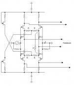
This is a JFET adaptation of the input stage of AMPZILLA III from J.Bongiorno.
It is conceived for full balanced bridge operation ( so it has four out and two feedback)
When point X is used as balanced input then RF2= RF1 and ry is cutted. Otherwise ( as in the figure) RF2= RF1+2*R
and ry is chosen so that ry // (2*RF2) = 2*RF1
I hope this helps
Federico
It is conceived for full balanced bridge operation ( so it has four out and two feedback)
When point X is used as balanced input then RF2= RF1 and ry is cutted. Otherwise ( as in the figure) RF2= RF1+2*R
and ry is chosen so that ry // (2*RF2) = 2*RF1
I hope this helps
Federico
Attachments
Thanks for your response Federico, but it does not really help. The cap in the original circuit play a large role in getting the impedance effect of the RC (to ground) network to correspond with a "balanced" calculation of the symetrical resistance values on both inverting and non-inverting input pins. See the pic below - although this does work, it is not acceptable as the non-inverting input impedance is severly effected.
I'm having difficulty getting the correct values for these combinations.
I'm having difficulty getting the correct values for these combinations.
Attachments
- Status
- This old topic is closed. If you want to reopen this topic, contact a moderator using the "Report Post" button.