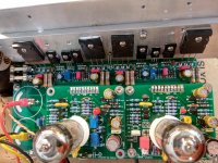
VSHA+I-AMP
Power supply=/-42V
Inp sensivity=130mV
Vout=26v RMS/6R
Pout=112W RMS.
Power supply=/-42V
Inp sensivity=130mV
Vout=26v RMS/6R
Pout=112W RMS.
Attachments
-
 IMG_20180822_125909_HDR.jpg423.3 KB · Views: 704
 -
 IMG_20180822_125438_HDR.jpg476.7 KB · Views: 698
 -
 IMG_20180822_125346_HDR.jpg439.3 KB · Views: 645
 -
 IMG_20180822_125117_HDR.jpg447.7 KB · Views: 615
 -
 IMG_20180822_125049_HDR.jpg483.1 KB · Views: 609
 -
 IMG_20180822_124915_HDR.jpg431.7 KB · Views: 95
 -
 IMG_20180822_124827_HDR.jpg447.5 KB · Views: 77
 -
 IMG_20180822_124423_HDR.jpg444 KB · Views: 95
 -
 IMG_20180804_122249_HDR.jpg950.2 KB · Views: 299
 -
 IMG_20180804_121940.jpg879 KB · Views: 315
Last edited:
Hi thimios
Very nice work as allways !!
Sorry for the delay, I am doing some major home renovation now and all my free time is gone
I hope next year Ill have some time for more DIY kind of work.
The voltage gain is huge (around 47 times) the plan was to use the amplifier without any preamplifier. Another thing is that the two ''cascoded'' differential amplifiers (one formed by ecc88 and second with two trannies) have really huge open loop gain so at the time I was playing with the circuit it was hard for me to tame it with a proper compensation.
If Ill have some more free time Ill try to rework the compensation to lower the total voltage gain of the amplifier.
Last edited:
The HD version for 12au7 tube is bellow (same as post no #23), heater is 6.3V ac , but you can cut one track and make it for 12DC.
I didn't have any problems with it but had some with 6n16b tube and had to add another compensation cap.
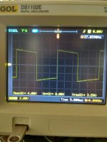
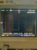
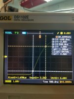
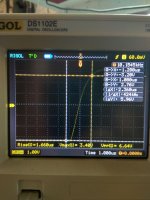
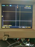
Just in case I have made a tests on v4 version too with additional miller cap at tranistor T1, amp is rock stable, no changes in performance.
Bellow few squares and triangles from it (2 x 47pF miller caps at the VAS stage)
Hi, I am a newbie in building solid state equipment, especially power amps. I am interested to build the VSHA classic because it is a ready tested design with the necessary files to fabricate the pcb.
From studying the schematic for the output stage, it appears that the mosfet source followers are biased by the 4 1n4148 diodes; so as to give approximately 2.4 to 2.6 volts across the gates of the n channel mosfet and the p channel mosfets.
Purpose of the 1k multiturn pot trimmer appears to me as being for further adjusting the bias voltage across the 2 gates by reducing the voltage between the 2 gates.
This is probably a stupid question to all you experienced builders here; but if I may ask, how is the voltage offset at the sources of the 2 mosfets trimmed to 0 volts? as there does not appear to be any off set adjustment?
I know that the 2 halves of each triode is not a perfect match and can never be. So how does one ensure that there is 0 volt offset at the output.
Perhaps someone can explain the output schematic to me.
Thanks
- Status
- This old topic is closed. If you want to reopen this topic, contact a moderator using the "Report Post" button.
- Home
- Amplifiers
- Solid State
- Very Simple Hybrid Ampifier